EPSON Stylus CX4300/CX4400/CX5500/CX5600/DX4400/DX4450 Revision A
DISASSEMBLY/ASSEMBLY Printer Section 70
REASSEMBLY OF SCANNER UNIT /MIDDLE CASE /PANEL UNIT
Installing the Panel Unit to the Middle Case
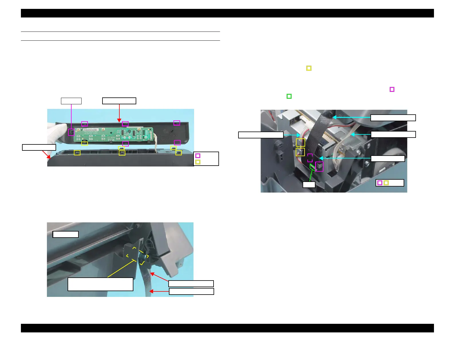
1. Put the Panel Unit cable through the cutout of the Middle Case.
(refer to Figure 4-19)
2. Slide the Panel Unit front-to-rear on the Middle Case engaging the tabs and hooks
shown below. Make sure to slide the Panel Unit until the tab A clicks and the unit
is secured.
Figure 4-20. Installing Panel Unit
3. Route the Panel Unit cable through the tabs (x4) on the backside of the Middle
Case. (refer to Figure 4-19)
Installing the Panel Unit/Scanner Unit/Middle Case to the Lower Case
1. Put the Scanner FFC and the Scanner Motor cable through the cutout of the
Middle Case.
Figure 4-21. Routing Scanner FFC and Scanner Motor Cable
2. Place the Panel Unit/Scanner Unit/Middle Case as shown in Figure 4-16.
3. Route and connect the cables/FFC to the Main Board Assy. as shown below. Refer
to Figure 4-27 for the connector layout on the Main Board.
• Scanner Motor cable: J6 connector on the Main Board
Route through the hooks (
x2) as shown.
• Scanner FFC: J5 connector on the Main Board
Put it through the ferrite core, and attach the core to the shield plate with
double-sided tape. Make sure to put the core under the hooks (
x2) and
on top of the rib (
x1).
• Panel Board: J3 connector on the Main Board
Figure 4-22. Connecting Scanner Motor Cable, Scanner FFC, Panel Cable
4. Secure the Middle Case (with the Panel Unit/Scanner Unit attached) to the Lower
Case engaging the left front tab (x1) (refer to Figure 4-15), then the tabs (x4) and
square holes (x4) on either sides. (refer to Figure 4-13, Figure 4-14)
5. Engage the right hinge of the Scanner Unit to the Lower Case (refer to Figure
4-12), then engage the left hinge of the Scanner Unit to the Lower Case and the
Middle Case. (refer to Figure 4-11)
6. Screw the Panel Unit/Scanner Unit/Middle Case to the Lower Case. (refer to
Figure 4-9, Figure 4-10)
Panel Unit
Middle Case
Hooks
Tabs
Tab (A)
Left side
Cutout for passing Scanner FFC
and Scanner Motor Cable
Scanner FFC
Scanner Motor cable
Scanner FFC
Scanner Motor cable
Panel Board cable
Hook
Ferrite Core
Rib
 Loading...


