Epson Stylus NX510/515/SX510W/515W/TX550W/NX415/SX410/415/TX410/419/NX215/SX210/215/TX210/213/219/ME OFFICE 510 Revision A
ADJUSTMENT Adjustment Items and Overview 162
Confidential
5.1 Adjustment Items and Overview
This chapter describes adjustments required after the disassembly/reassembly of the
printer.
5.1.1 Servicing Adjustment Item List
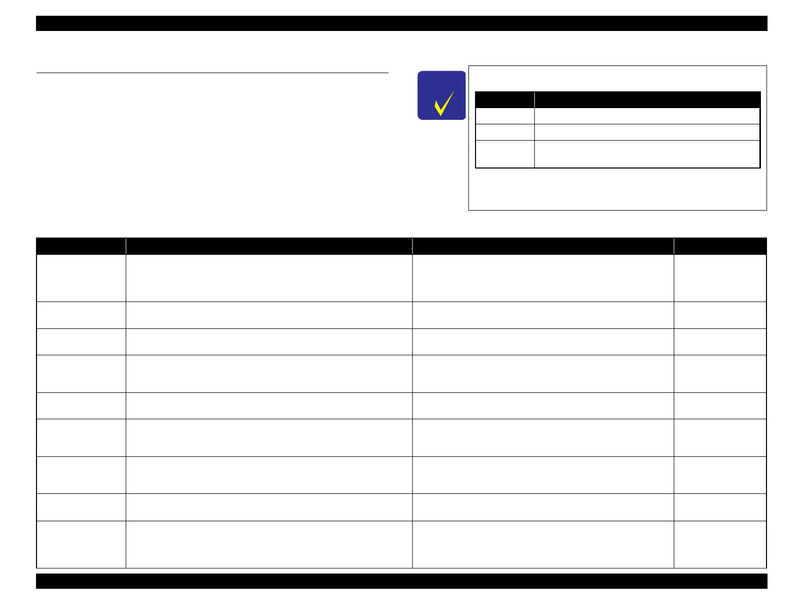
The adjustment items of this product are as follows.
In this chapter, the product names are called as follows:
For information on how to carry out the adjustments and
media required for the adjustments, see the instructions
displayed by the Adjustment Program.
Notation Product name
NX510 series Epson Stylus NX510/NX515/SX510W/SX515W/TX550W
SX410 series Epson Stylus NX415/SX410/SX415/TX410/TX419
SX210 series
Epson Stylus NX215/SX210/SX215/TX210/TX213/
TX219/ME OFFICE 510
Table 5-1. Adjustment Items
Adjustment Item Purpose Method Outline Tool
EEPROM data copy
When the main board needs to be replaced, use this to copy adjustment
values stored on the old main board to the new board. If this copy is
completed successfully, all the other adjustments required after replacing the
main board are no longer be necessary.
Readout the EEPROM data from the main board before removing it.
Then replace the board with a new one, and load the EEPROM data to
the new board.
• Adjustment Program
Initial setting
This must be carried out after replacing the main board to apply settings for
the target market.
Select the target market. The selected market settings are
automatically written to the main board.
• Adjustment Program
USB ID input
This sets a USB ID of the printer. A computer identifies the printer by the ID
when multiple same models are connected via a USB hub.
Enter the product serial number of the printer. The ID is automatically
generated and written to the main board.
• Adjustment Program
Head ID input
This must be carried out after replacing the Printhead in order to enter the
new Printhead ID (Head ID) that reduces variation between Printheads.
Enter the ID printed on the Head QR code label attached on the
Printhead. The correction values are automatically written to the main
board.
• Adjustment Program
MAC address
read/write
*1
When the Main board needs to be replaced use this menu to write necessary
information onto the new board.
See “ 5.2.8 MAC Address Setting (NX510 series only) (p173) ”for the
detailed procedure.
• Adjustment Program
• USB Cable
TOP margin
adjustment
This corrects top margin of printout. A top margin adjustment pattern is printed. Examine the lines printed
near the top edge of the printout, and enter the value for the line that
is exactly 3 mm away from the top edge.
• Adjustment Program
•Ruler
First dot position
adjustment
This corrects left margin of printout. The print start position in the carriage
moving direction is corrected by software.
A first dot adjustment pattern is printed. Examine the lines printed
near the left edge of the printout and enter the value for the line that is
exactly 5 mm away from the left edge.
• Adjustment Program
•Ruler
Head angular
adjustment
This must be carried out after replacing the Printhead in order to correct tilt
of the Printhead by software.
A head angular adjustment pattern is printed. Examine the printed
lines and enter the value for the most straight lines.
• Adjustment Program
Bi-D adjustment
This corrects print start timing in bi-directional printing to improve the print
quality.
A Bi-D adjustment pattern is printed. Black and color patterns are
printed for each of the five dot sizes (ECO, VSD1, VSD2, VSD3,
VSD4). So, there are 10 groups. Examine the patterns and enter the
value for the pattern with no gap and overlap for each mode.
• Adjustment Program
 Loading...