Epson Stylus SX230 series / SX235W series / SX430W series / SX440W series Revision B
Disassembly/Reassembly Routing FFCs/cables 39
Confidential
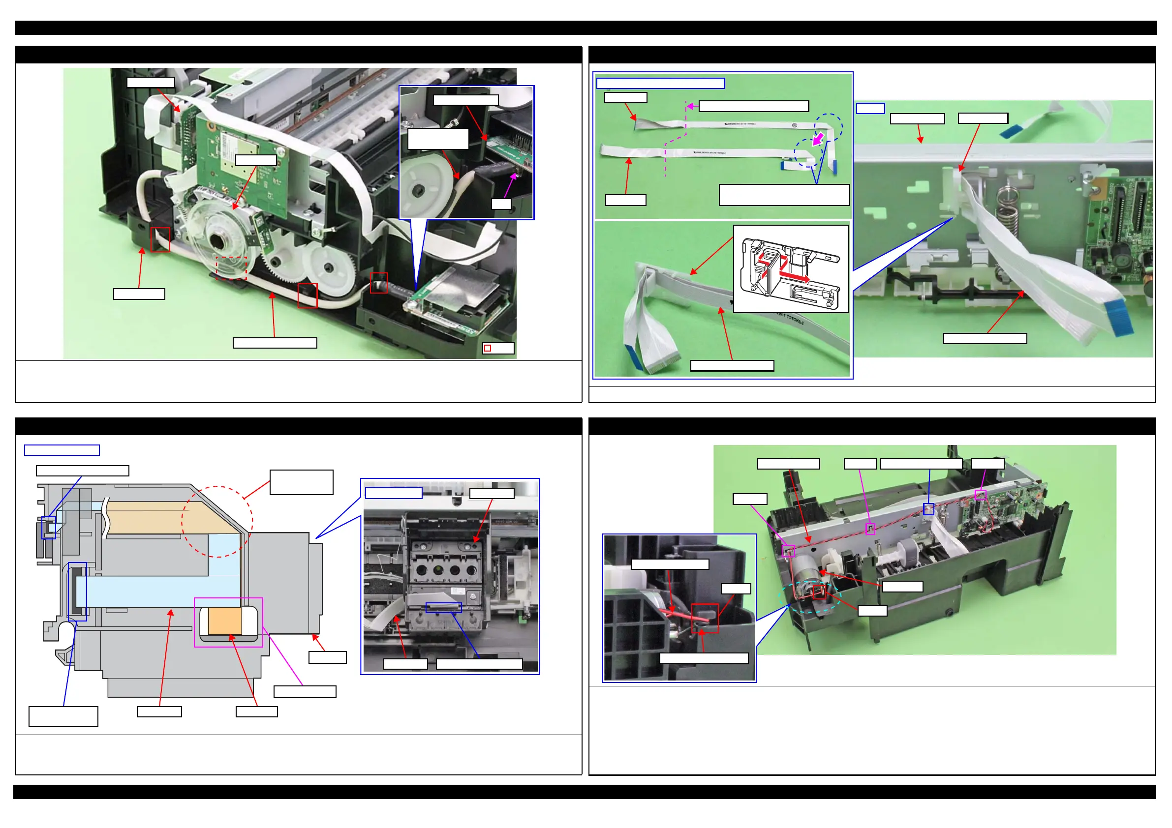
Card Slot Board (SX230 series/SX430W series/SX440W series)
When routing the Card Slot Board cable, be careful not to damage the PF Scale.
Route the Card Slot Board cable through the ribs (x4) of the Frame Base.
Connect the connectors on both ends of the Card Slot Board cable to the Card Slot Board (CN3) and Main Board (CN9) firmly. (p 38)
Frame Base
Main Board
PF Scale
Rib
Card Slot Board
Card Slot Board
cable
CN3
Head FFC (1)
Align the Head FFC and CSIC FFC, and then route them through the FFC Holder as shown in the figure above.
Aligning Head FFC with CSIC FFC
Head FFC
CSIC FFC
Stack the Head FFC over the CSIC
FFC to keep the Head FFC on top.
Fold here inside FFC Holder
Rear
FFC Holder
Head FFC/CSIC FFC
Main Frame
FFC Holder
Head FFC/CSIC FFC
Head FFC (2)
Route the Head FFC and CSIC FFC through the CR Unit as shown in the figure above, and then connect them to the Printhead, CR Encoder Sensor and
Holder Board Assy.
Be careful not to damage the Head FFC when routing it through the hole of the CR Unit.
Head FFC
Printhead
Inside CR Unit
Connector of Printhead
CSIC FFC Head FFC
CR Unit
Connector of CR Encoder
Connector of CR
Contact Module
Put Head FFC
over CSIC FFC
Hole of CR Unit
Left side of CR Unit
CR Motor
Route the CR Motor cable as follows before installing the Shield Plate.
1. Route the CR Motor cable (black) around the rib A of the Frame Base (two turns).
2. Route the CR Motor cable (red) through the rib B of the Frame Base, and then route it through the rib A taking care not to let the CR Motor cable (red)
come over the CR Motor cable (black).
3. Twist the CR Motor cable (black) and CR Motor cable (red) twice, and then route them through the hook C of the Main Frame.
4. Route the CR Motor cable (black) and CR Motor cable (red) in the order of hook D of the Main Frame, groove of the FFC Holder, and hook E of the Main
Frame.
CR Motor
Hook C
Hook EGroove of FFC HolderCR Motor cable Hook D
Rib A
CR Motor cable (black)
CR Motor cable (red)

 Loading...