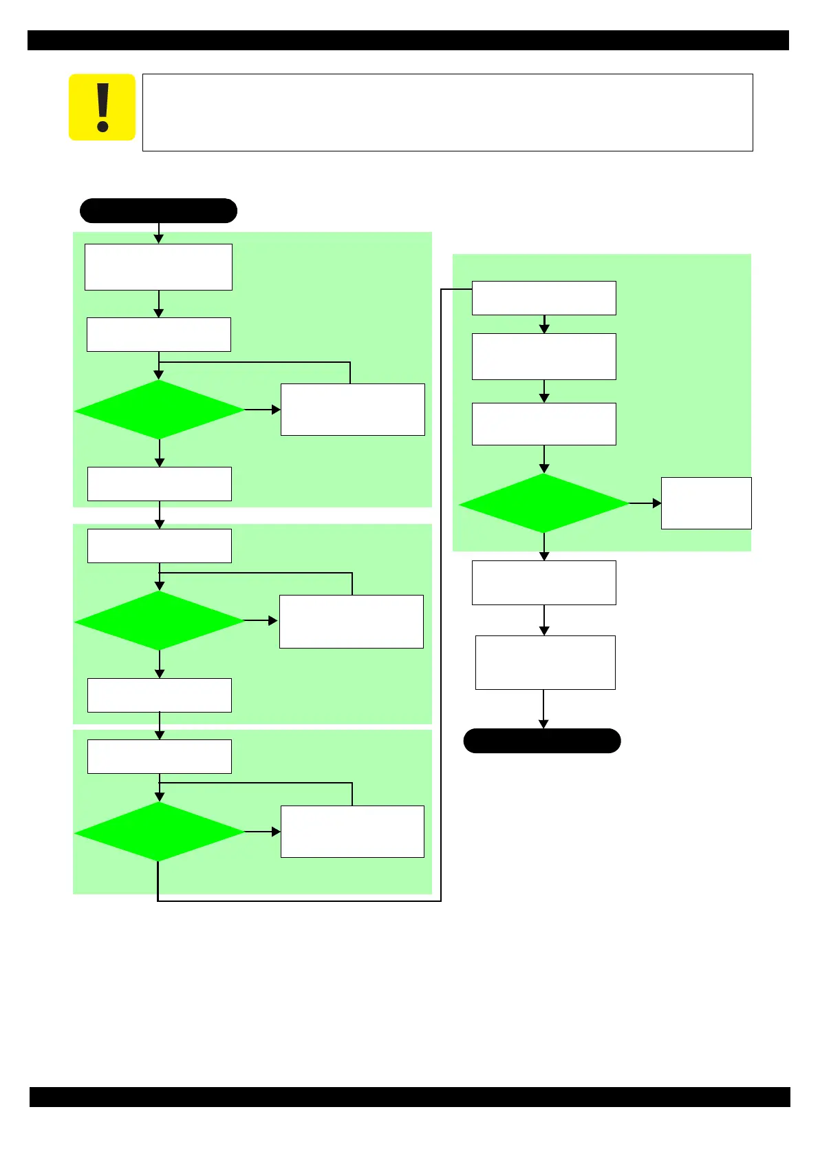
9. Follow the flowchart below to perform the PG adjustment.
Figure 3-27. PG Adjustment Flow
Frame. (See Figure 3-24 (p 72).)
START
Move the Carriage Assy to
the 0-digit side.
Yes
No
Move the Carriage Assy to
the center of the printer.
Move the Carriage Assy to
the center, and adjust one
notch for PG Cam Right to
make the PG wider.
Yes
No
Yes
No
Yes
No
Remove the PG Cam Right/
Left once, and attach them
back on the same positions
as shown in Step 1. (p 71).
Return to Step 7.
(p 73) and
perform the
adjustment again.
END
Change the thickness gauges
(x2) to 1.37 mm ones that the
teflon tape attached.
Adjusts the PG to more than
1.45 mm on the 0-digit side.
Move the Carriage Assy to
the center of the printer.
Move the Carriage Assy to
the 80-digit side.
Move the Carriage Assy to
the 0-digit side.
Move the Carriage Assy to
the center of the printer.
Change the thickness gauges
(x2) to 1.47 mm ones that
the Teflon tape attached.
Move the Carriage Assy to
the 0-digit side and to the
80-digit side.
Does the Carriage
Assy touch the
thickness gauges?
Does the Carriage
Assy touch the
thickness gauges?
Does the Carriage
Assy touch the
thickness gauges?
Does the Carriage
Assy touch the
thickness gauges?
Adjusts the PG to more than
1.45 mm on the 80-digit side.
Confirms the PG is more than
1.45 mm on the 0-digit side.
Confirms the PGs are less
than 1.55 mm on the 0-digit
side and 80-digit side.
Secure the CR Guide Frame
with the screws (x3).
(See Figure 3-22 (p 71).)
Move the Carriage Assy to
the center, and adjust one
notch for PG Cam Left to
make the PG wider.
Move the Carriage Assy to
the center, and adjust one
notch for PG Cam Right to
make the PG wider.
 Loading...