4
GB
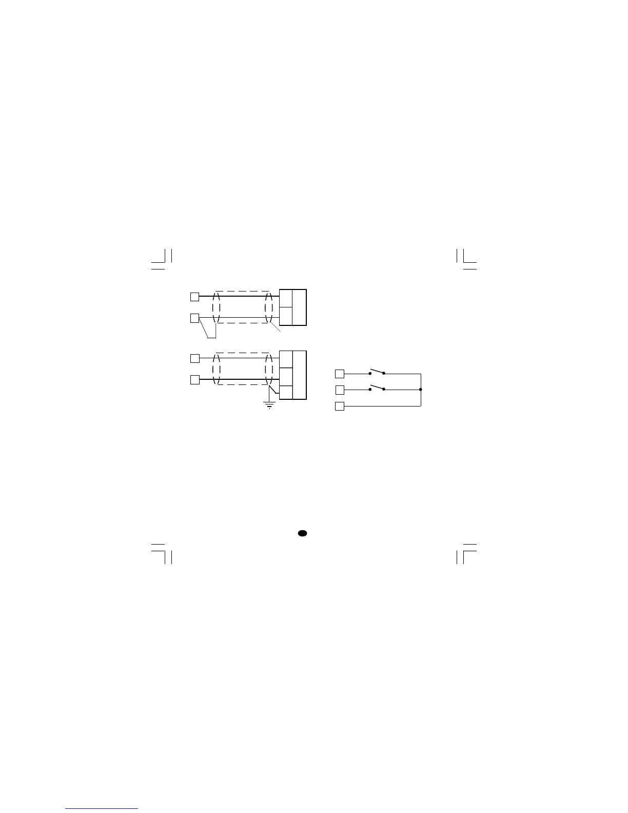
LINEAR INPUT
Fig. 5 mA, mV AND V INPUTS WIRING
NOTE:
1) Don’t run input wires together with power
cables.
2) Pay attention to the line resistance; a high line
resistance may cause measurement errors.
3) When shielded cable is used, it should be
grounded at one side only to avoid ground loop
currents.
4) The input impedance is equal to:
< 5 Ω for 20 mA input
> 1 MΩ for 60 mV input
> 400 kΩ for 5 V input
> 400 kΩ for 10 V input
LOGIC INPUT
Safety note:
1) The "serial comunication" and the "logic input"
options are mutually exclusive.
2) Do not run logic input wiring together with
power cables.
3) Use an external dry contact capable of
switching 0.5 mA, 5 V DC.
4) The instrument needs 100 ms to recognize a
contact status variation.
5) The logic inputs are isolated by the measuring
input
Fig. 7 - LOGIC INPUT WIRING
This instrument is provided with 2 logic inputs.
The logic input 1 allows to select the operative set
point as follows
logic input 1 op. set point
open SP
close SP2
The logic input 2 allows to select the AUTO /
MANUAL operative mode (see also P24
parameter):
logic input 2 operat. mode
open AUTO
close MANUAL
Shield
_
+
mA,
mV
or
V
9
+
_
G
mA
mV
or
V
10
9
10
11
Log. input 1
12
13
Log. input 2
LFS-servo-1-02.p65 1/14/02, 3:43 PM4