5
GB
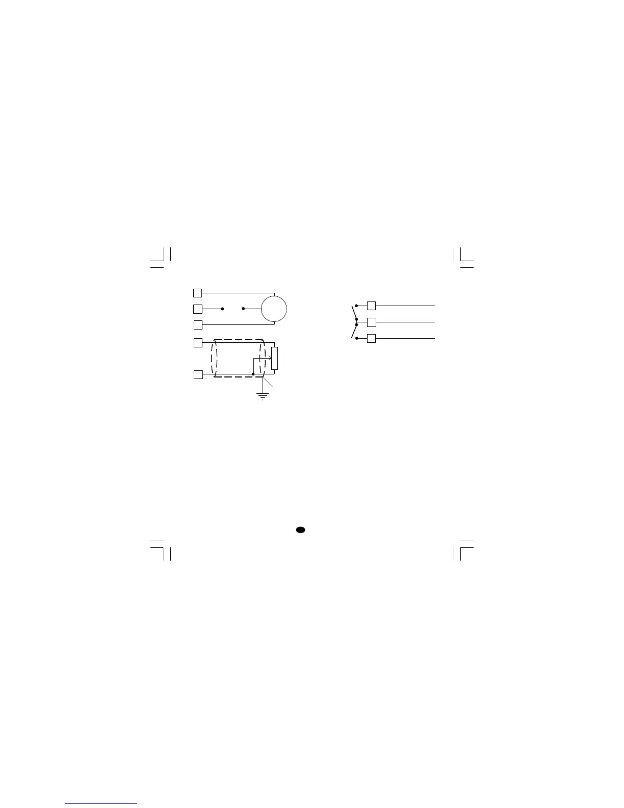
VALVE MOTOR DRIVE OUTPUT.
Fig. 8 - SERVOMOTOR WIRING
The two relay outputs are interlocked.
NOTE:
1) Before connecting the instrument to the power
line, make sure that line voltage and the load
current are in accordance with the contact rating
(3A/250V AC on resistive load).
2) To avoid electric shock, connect power line at the
end of the wiring procedure.
3) For servomotor connections use No 16 AWG or
larger wires rated for at last 75 °C.
4) Use copper conductors only.
5) Don’t run input wires together with power cables.
6) For feedback potentiometer, use shielded cable
with the shield connected to the earth at one point
only.
7) The relay outputs are protected by varistor
against inductive load with inductive compo-
nent up to 0.5 A.
1
2
3
Servo-
motor
Power
line
s (Open the valve)
t (Close the valve)
RELAY OUTPUTS
Fig. 9 RELAY OUTPUTS WIRING
NOTE: OUT 1 can be used either as servomotor
output or as time proportional relay output;
by the P5 parameter (see pag.11) it is
possible to set the desired output.
All relay outputs are protected by varistor against
inductive load with inductive component up to 0.5 A.
The contact rating of the OUT 3 and 4 is 2A/250V AC
resistive load.
The number of operations is 1 x 10
5
at specified
rating.
Alarm 2 and alarm 3 are in OR condition on the
out 4.
The following recommendations avoid serious
problems which may occur, when using relay
output for driving inductive loads.
8
6
7
C - OUT 3/4
NO - OUT 4
NO - OUT 3
OUT 4
OUT 3
14
15
Feedback
potentiometer
Shield
LFS-servo-1-02.p65 1/14/02, 3:43 PM5