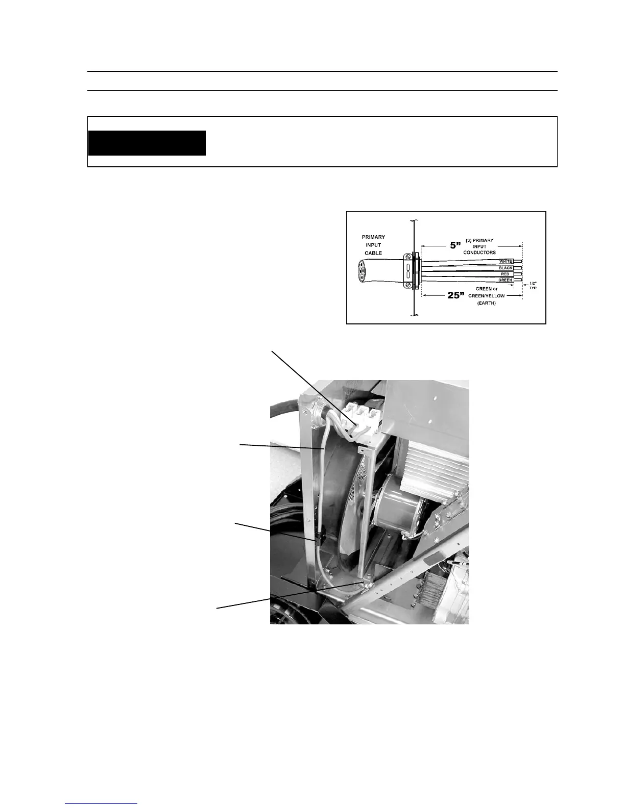
C. Thread the properly stripped input and ground conduc-
tors through the large strain relief in the rear panel of the
power source. Connect the three input conductors to the
three input terminals on TB3 (see figure 2-1). To connect
the ground conductor, thread the ground wire through the
ground fault switch bracket and connect to the ground lug
provided on the A-Frame.
D. Check all connections for proper tightness. Ensure all con-
nections are correct and well-insulated.
Recommended Cable Strip Lengths
Primary Cable
(Supplied by
Customer)
Ground Fault
Switch & Bracket
TB-3
L1, L2, L3
Connection
Ground
Connection
THE CHASSIS MUST BE CONNECTED TO AN APPROVED ELECTRICAL
GROUND. FAILURE TO DO SO MAY RESULT IN ELECTRICAL SHOCK,
SEVERE BURNS OR DEATH.
SECTION 3 INSTALLATION
WARNING
Figure 3-1. Connecting Primary Power Leads