36
1. Tighten the bolts evenly until finger tight noting that the nuts are not rotating.
2. Tighten the bolts 3/4 turn plus an 1/8 turn using a socket wrench on the bolt heads and rotating only in 1/4 turn incre-
ments plus 1/8 turn alternating between the bolts noting that the nuts are not rotating.
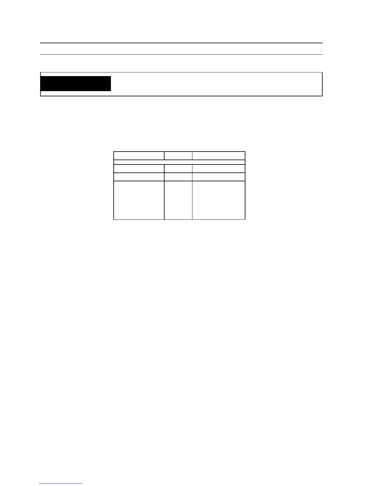
Table 6-1. PCB Voltage Tests*
NOTE:
All voltage readings are taken with the front access panel open and the power switch "ON".
* Refer to Schematic Diagram
** Varies with VCP (R1)
SECTION 6 TROUBLESHOOTING
WARNING
ELECTRICAL SERVICE AND REPAIR SHOULD BE ATTEMPTED ONLY BY
A TRAINED ELECTRICIAN.
FROM TO READING
P8-5 OTB+ +10 V dc
P8-7 OTB+ 0-10 V dc**
P6-6 (SCR1)
P6-5 (SCR2)
P6-4 (SCR3)
P6-3 (SCR4)
P6-2 (SCR5)
P6-1 (SCR6)
OTB+ .3 V dc with
contactor on