-- 2 4 --
dha4d1ea
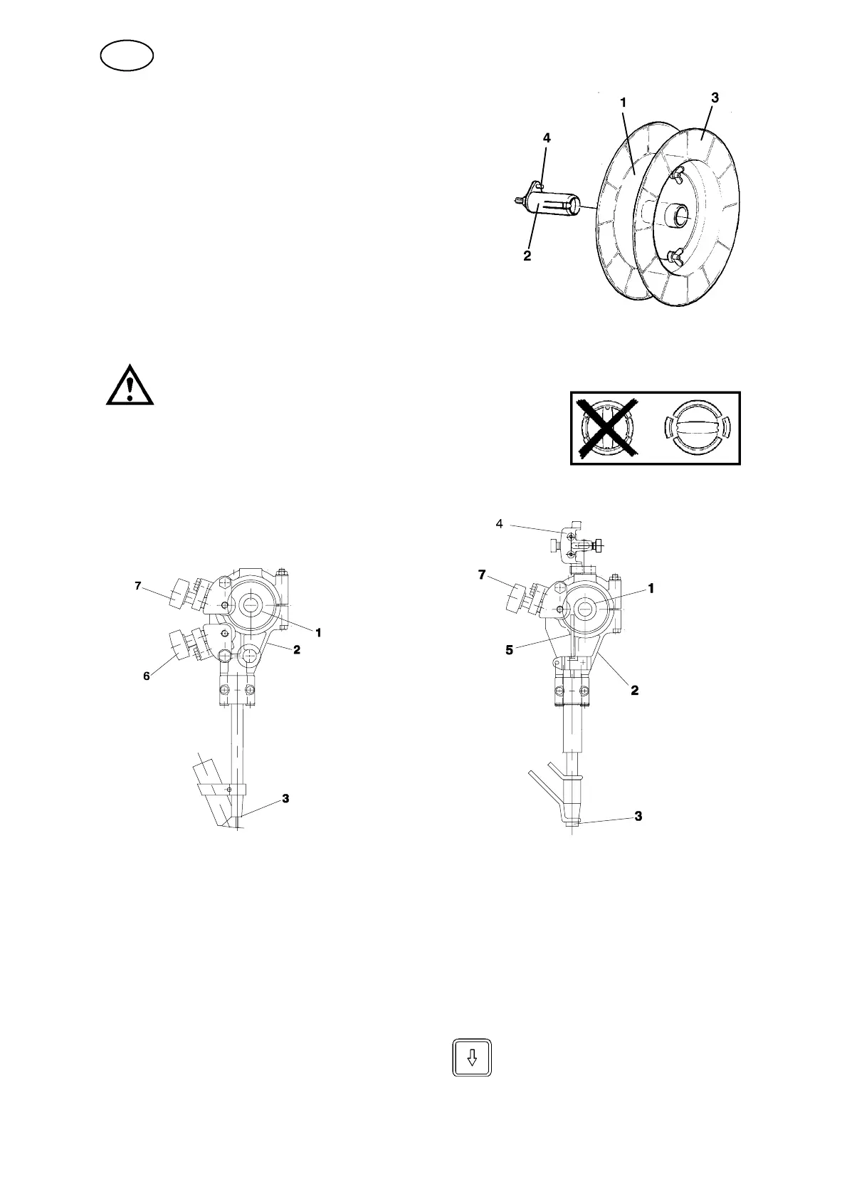
2. Loading the welding wire
S Remove the wire drum (1) from the brake hub (2)
and take off the side plate (3).
S Locate the wire reel on the wire drum (1).
S Cut off the binding wires from around the
wire reel.
S Replace the side plate (3).
S Replace the wire drum (1) on the brake hub (2).
Check that the carrier (4) is in the correct position.
NOTE! The maximum angle for the wire bobbin is 25°.
At extreme angles, wear will occur on the brake hub locking
mechanism and the wire bobbin will slide off the brake hub.
IMPORTANT!
To prevent the reel sliding off the hub: Lock the reel in place
by turning the red knob as shown on the warning label atta-
ched next to the hub.
SAW MIG/MAG
S Check that the feed roller (1) and contact jaw or contact tip (3) are of the correct
dimension for the selected wire size.
S Pull the end of the wire through the straightener (2). For a wire diameter greater
than 2 mm; straighten out 0.5 m of wire and feed it by hand down through the
straightener.
S Locate the end of the wire in the feed roller (1) groove.
S Set the wire tension on the feed roller with the knob (7). Note! Do not tension
more than is required to achieve an even feed.
S Feed the wire forward 30 mm by pressing on the control box A2--A6
Process Controller.
GB