-- 7 6 --
ffa9d1ea
7 FAULT TRACING
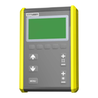
Equipment S Instruction manual for control box A2--A6 Process Controller.
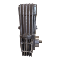
S Operating manual for m otor with gear A6 VEC,
order no. 0443 393.
Check S that the power source is connected for the correct mains supply
S that all three phases are live (phase sequence is not important)
S that welding cables and connections are not damaged
S that the controls are correctly set
S that the mains supply is disconnected before starting repairs
POSSIBLE FAULTS
1. Symptom Current and voltage readings show large fluctuations
Cause 1.1 Contact jaws or nozzle are worn or wrong size.
Action Replace contact jaws or nozzle.
Cause 1.2 Feed roller pressure is too low.
Action Increase pressure on feed rollers.
2. Symptom Wire feed is irregu lar
Cause 2.1 Feed roller pressure not correct.
Action Change the feed roller pressure.
Cause 2.2 Feed rollers wrong size.
Action Replace feed rollers.
Cause 2.3 Grooves in feed rollers are worn.
Action Replace feed rollers.
3. Symptom Welding cables overheating
Cause 3.1 Poor electrical connection.
Action Clean and tighten all electrical connections.
Cause 3.2 Cross--section of welding cables too small.
Action Use cables with a larger cross--section or use parallel cables.
GB