Do you have a question about the ESAB Aristo U8 and is the answer not in the manual?
Details on what is included with the U8 unit.
Initial setup and language selection upon first machine start.
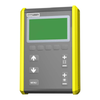
Explanation of the controller display, cursor, and text boxes.
Description of arrow keys, menu key, and plus/minus keys for operation.
Covers numerical, fixed option, and ON/OFF/YES/NO settings.
Functions of the ENTER and QUIT soft keys for navigation.
Access to change weld process, method, wire type, and other submenus.
Diagram illustrating the hierarchical flow of the controller menus.
Configuration parameters for MIG/MAG welding processes.
Detailed explanations for various MIG/MAG welding parameters.
Configuration parameters for MMA welding processes.
Detailed explanations for various MMA welding parameters.
Configuration parameters for TIG welding processes.
Detailed explanations for various TIG welding parameters.
Configuration parameters for Carbon, Arc Air welding.
Explanations for Carbon, Arc Air welding parameters.
Information on compatible wire and gas types for Aristo SuperPulse.
Overview of different pulsing methods based on material thickness.
Configuration settings for Aristo SuperPulse welding.
Explanations for Aristo SuperPulse specific functions.
How the controller's memory units (primary and weld data) function.
Step-by-step guide on how to save weld data settings.
Procedure for deleting stored weld data sets.
Steps to retrieve stored weld data settings.
Instructions on how to copy weld data to other memory positions.
Manages data on internal memory and flash cards (saving, deleting, recalling).
Explains the information in the first block of quality data files.
Describes the meaning of different values in the ChangeStatus column.
Details the meaning of each digit in the ChangeStatus column.
How to describe and manage welding data schedules.
Example of saving welding data configurations to a compact flash card.
Enables/disables password protection for certain menus.
How to enable/disable the lock function and set/change the code.
Procedure for editing or entering a new lock code.
Settings for connecting and configuring remote control devices.
Function to automatically recall last settings before each weld.
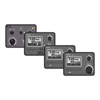
Configuration options for digital remote controls.
Configuration for analogue potentiometers (voltage, wire speed).
Setting control ranges (min/max) for potentiometers.
Default settings for MIG/MAG welding processes.
Settings for 2-stroke and 4-stroke trigger control modes.
Assigning functions to the controller's soft keys.
Options for measuring voltage in dip welding (peak/average).
Customizing 4-stroke start and stop functions.
Default settings for MMA welding processes.
Setting the current level for the hot start function.
Adjusting the time duration for the hot start function.
Optimizing heat supply for starting on hot material.
General machine configuration settings.
Configuring soft keys for quick access to weld data.
Enabling simultaneous start from multiple inputs.
Allowing panel controls to function in remote mode.
Automatic saving of settings when recalling new data.
Switching between weld data sets using the torch trigger.
Enabling continuous saving of weld quality data to a flash card.
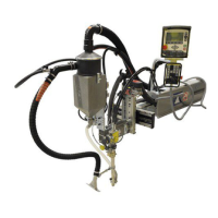
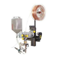
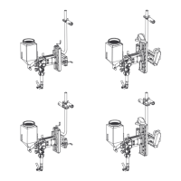
Configuring and connecting multiple wire feeders to the unit.
Connecting specific weld data to active wire feeders.
Selecting between metric and inch units for length measurements.
Procedure for saving recorded quality data onto a memory card.
Options for removing specific or all error messages from the log.
Displays a summary of all registered error messages.
A comprehensive list of error codes and their associated components.
Detailed explanations and troubleshooting actions for error codes.
Steps to define voltage and wire speed points for synergic lines.
Specific process for defining dip/spray synergic line coordinates.
Specific process for defining pulse synergic line coordinates.
Associating defined synergic lines with wire and gas types.
Extending available wire/gas options with custom entries.
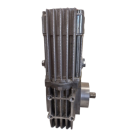
Information on the ESAB Logic Pump function and its integration.
Specific combinations for DIP/SPRAY welding.
Specific combinations for PULSE welding.
Electrode types and diameters for MMA welding.
Electrode diameters for Carbon, Arc Air welding.
| Category | Welding Accessories |
|---|---|
| Type | Wire feeder |
| Display | Digital |
| Wire Feed Speed Range | 0.5 - 25 m/min |
| Input Current | 16 A |
| Wire Diameter Range | 0.6 - 1.6 mm |