-- 1 2 --
bi09dinte
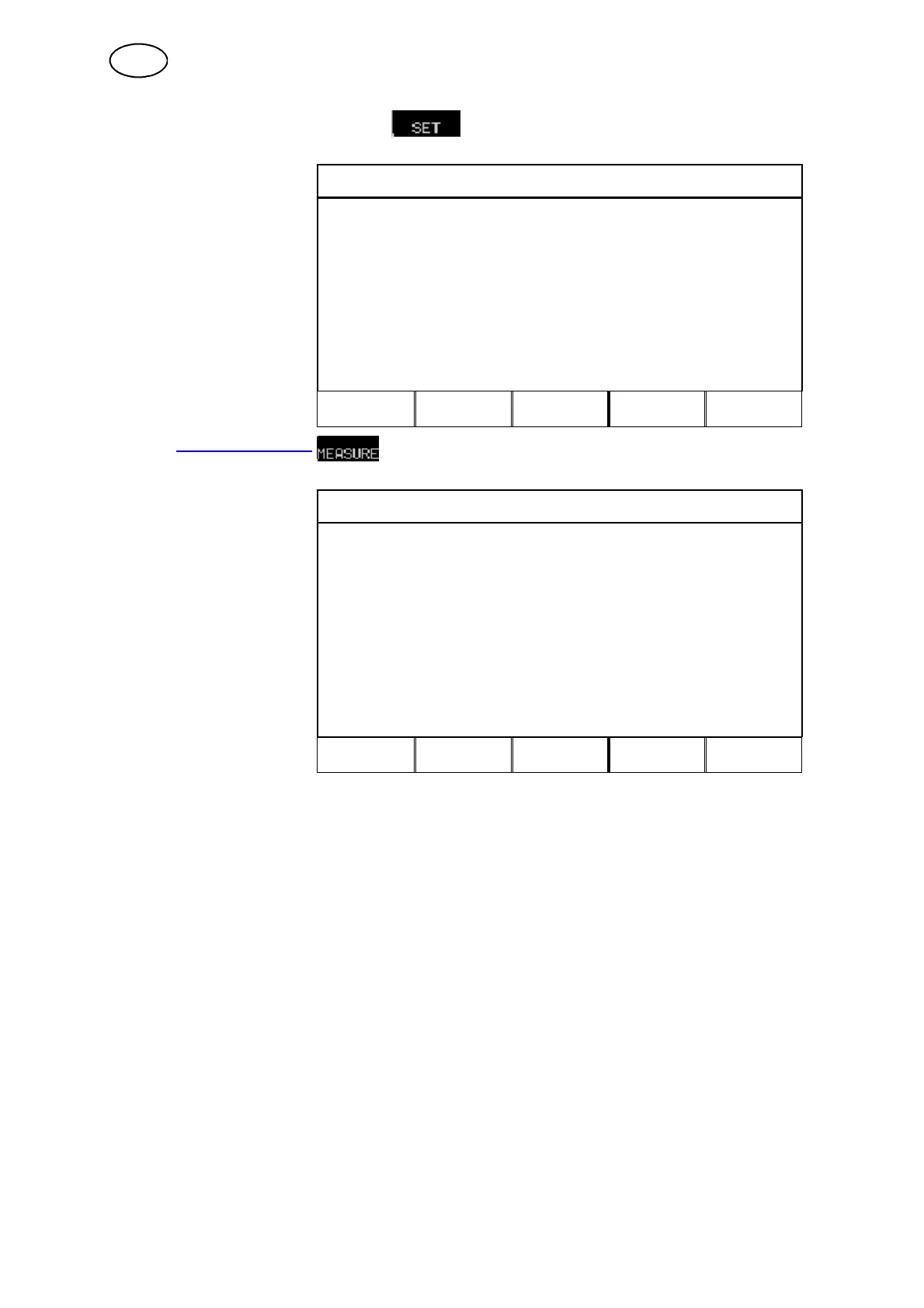
2.1.2 Weld data setting menu
In the WELD DATA
WELD DATA SETTING
you can
change various weld
parameters. The menu’ s
appearance differs,
depending on which weld
process you have selected.
In this example it is
MIG/MAG welding with
dip/spray.
VOLTAGE: # 26.8 (+0.0) V
WIRE SPEED: * 6.0 m/min
INDUCTANCE: 80 %
SYNERGIC MODE PÅ
START DATA...
STOP DATA...
LIMITS
CRATR
FILL
HOT
START
4--
STROKE
QUIT
2.1.3 Measure image
In the MEASURE IMAGE
DIP/SPRAY. Fe, CO2, 1.2 mm
you can see
e measure
values of various weld
parameters during welding.
The measured values
remain in the display even
after welding has been
completed.
You can move to other
menus without losing the
measured values.
# 0.0 Volt
0Amp
* 6.0 m/min
↓
CRATER
FILL
HOT
START
4--
STROKE
REM
2ND
FUNCT
The arrow in the bottom right--hand corner of the display indicates that there is more
information available.
In the measure image you can change the value of certain parameters. Which
parameters these are depends on which weld process has been set. The parameter
values that can be adjusted are always marked with # or *.
When values are changed while no welding is in progress, the measured values will
change to zero to avoid misunderstandings regarding which settings correspond to
the measure result.
TIP!
In pulsing you can select whether the voltage value is displayed as an average value
or peak value. This setting can be defined under MIG/MAG basic settings, see
chapter 12.3.
GB