© ESAB AB 2008
- 8 -
bh32d1e
4 INSTALLATION
The installation must be executed by a professional.
Note
Mains supply requirements
High power equipment may, due to the primary current drawn from the mains supply, influence the
power quality of the grid. Therefore connection restrictions or requirements regarding the
maximum permissible mains impedance or the required minimum supply capacity at the interface
point to the public grid may apply for some types of equipment (see technical data). In this case it
is the responsibility of the installer or user of the equipment to ensure, by consultation with the
distrubution network operator if necessary, that the equipment may be connected.
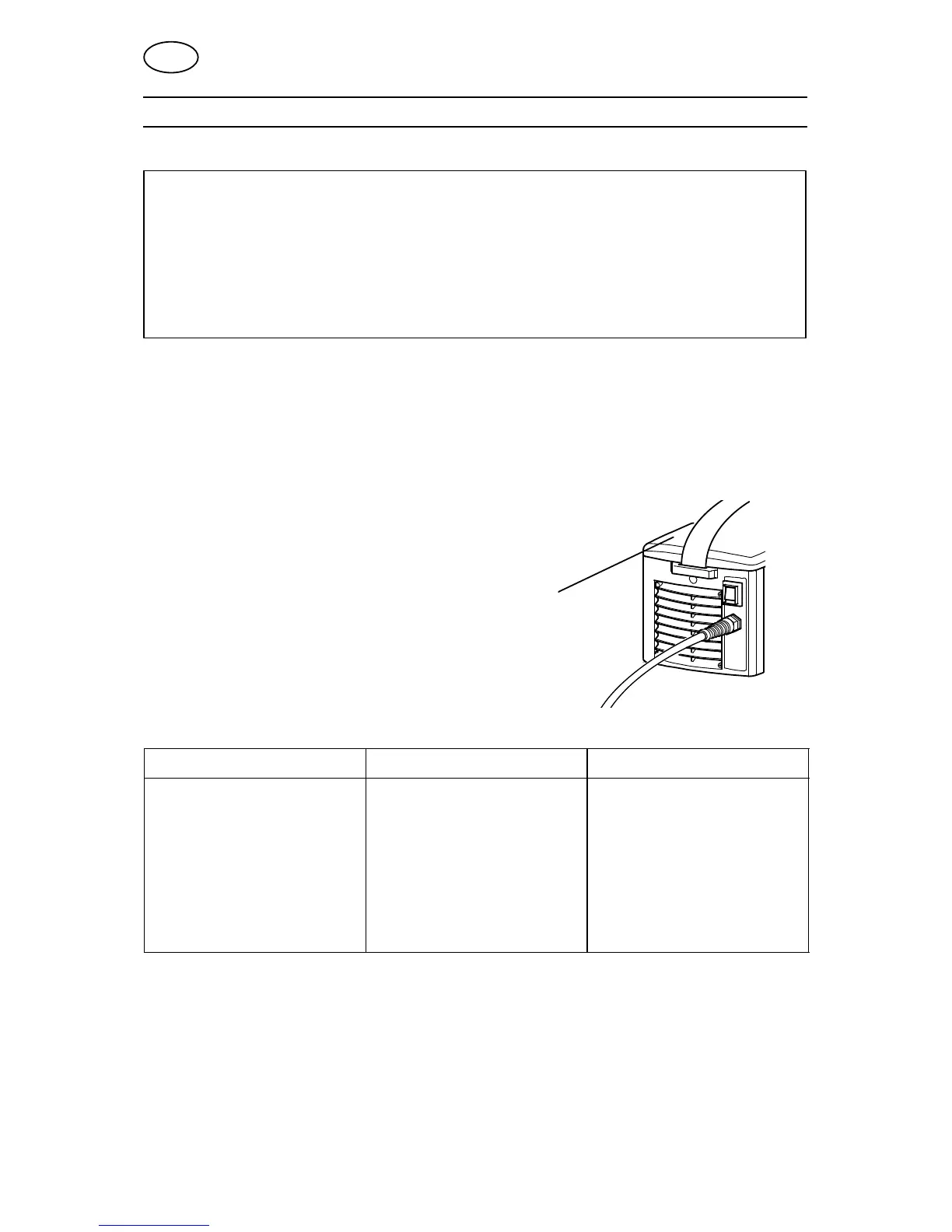
4.1 Location
Position the power source such that its cooling air inlets and outlets are not
obstructed.
4.2 Mains power supply
Check that the welding power source is connected
to the correct voltage and that the correct fuse size
is used. A protective earth connection must be
made in accordance with regulations
Location of rating plate
4.2.1 Recommended fuse sizes and minimum cable area
Arc 151i Arc 201i
Mains voltage 230 V 10 %, 1-phase 230 V 10 %, 1-phase
Mains frequency 50-60 Hz 50-60 Hz
Mains cable, area 3G2.5 mm
2
3G2.5 mm
2
Phase current I
1eff
11.5 A 13.4 A
Welding cable, area 16 mm
2
16 mm
2
Fuse
anti-surge
type C MCB
16 A
13 A
16 A
16 A
NOTE!
The cable area and fuse rating above comply with Swedish regulations. Use the
welding power source in accordance with the relevant national regulations.
GB