Do you have a question about the ESAB EMP 205ic AC/DC and is the answer not in the manual?
Explains warning symbols used in the manual.
General safety instructions for operating welding equipment.
Defines the operator's duties and responsibilities for safe equipment use.
Provides specific warnings related to California Proposition 65.
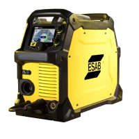
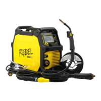
Lists all the components and accessories supplied with the welding unit.
Describes the unit's automatic overheating protection system.
Details the technical specifications and performance data for the EMP 205ic AC/DC.
Instructions on positioning the welding power source for optimal cooling.
Warnings and precautions regarding high frequency interference from the unit.
User's responsibility for managing electromagnetic disturbances and installation.
Factors to consider when assessing the work area for electromagnetic interference.
Guidance on how to safely lift and move the welding power source.
Requirements and considerations for connecting the welding unit to the mains power supply.
Specifies recommended electrical service parameters for safe and efficient operation.
Guidelines for using power generators to supply the welding unit.
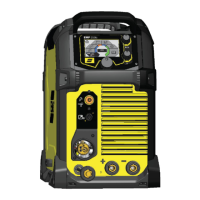
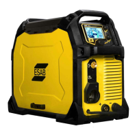
Identifies and explains the function of all front and rear panel controls and connections.
Instructions for connecting welding and return cables for MIG/MMA and TIG processes.
How to change the polarity setting for different welding processes.
Guidance on selecting and using appropriate shielding gases for various materials.
Explains the purpose of volt-ampere curves shown in the manual.
Displays the volt-ampere curve for SMAW welding at 120V.
Displays the volt-ampere curve for SMAW welding at 230V.
Displays the volt-ampere curves for GMAW (MIG) welding at 120V.
Displays the volt-ampere curves for GMAW (MIG) welding at 230V.
Displays the volt-ampere curves for GTAW (DC TIG) welding at 120V.
Displays the volt-ampere curves for GTAW (DC TIG) welding at 230V.
Displays the volt-ampere curves for GTAW (AC TIG) welding at 120V.
Displays the volt-ampere curves for GTAW (AC TIG) welding at 230V.
Explains the concept of duty cycle and its relation to welding current and time.
Details the 25% duty cycle operation and provides a graphical example.
Step-by-step instructions for removing and installing the wire bobbin.
Introduces the process of handling the welding wire.
Provides instructions for safely removing wire from the unit.
Specific instructions and considerations for welding with aluminum wire.
Guide on how to adjust and set the correct wire-feed pressure.
Instructions for removing and installing wire-feed rollers.
Steps to remove a wire-feed roller from the assembly.
Steps to install a wire-feed roller onto the assembly.
Explains how to navigate through the control panel menus and options.
Lists and describes the primary options available in the main menu.
Details the interface and functions of the basic SMIG mode.
Details the interface and functions of the advanced SMIG mode.
Details the interface and functions of the basic Manual MIG mode.
Details the interface and functions of the advanced Manual MIG mode.
Details the interface and functions of the basic Flux cored wire mode.
Details the interface and functions of the advanced Flux cored wire mode.
Details the interface and functions of the basic MMA mode.
Details the interface and functions of the advanced MMA mode.
Details the interface and functions of the basic DC TIG mode.
Details the interface and functions of the advanced DC TIG mode.
Details the interface and functions of the basic AC TIG mode.
Details the interface and functions of the advanced AC TIG mode.
Accessing and adjusting various machine settings and preferences.
Accessing information related to maintenance, parts, and operation from the menu.
Explains the meaning of various icons displayed on the control panel.
Explains the DC TIG Pulse welding mode and its parameters.
Explains the AC TIG welding process, its applications, and parameters.
Illustrates the 2-stroke and 4-stroke processes for Lift-TIG welding.
Outlines the schedule for performing routine maintenance tasks on the equipment.
General maintenance procedures for the wire-feeder assembly.
Steps for cleaning the wire-feeder assembly.
Maintenance advice for the power supply side of the unit, emphasizing professional service.
Procedures for maintaining the torch liner.
Steps for cleaning the torch liner.
Initial troubleshooting steps and checks before contacting service.
Lists and explains error codes displayed by the user interface for troubleshooting.
Provides a schematic of the unit's functional block diagram.
| Output Range DC | 5-200 A |
|---|---|
| Output Current Range | 5-200 A |
| Output Current Range TIG | 5-200 A |
| Protection Class | IP23S |
| AC Frequency | 20 - 250 Hz |
| Output Range AC | 20-200 A |
| Duty Cycle @ 200A | 25% |
| Duty Cycle TIG | 25% @ 200 A |
| Welding Processes | MMA, TIG |
| Pulse Frequency | 0.1-500 Hz |