EasyManua.ls Logo

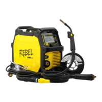
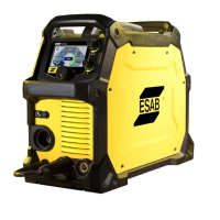
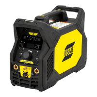
ESAB Rebel EMP 215ic User Manual

ESAB Rebel EMP 215ic
66 pages
To Next Page IconTo Next Page
Page #1 background imageLoading...
Page #1 background image
Rebel EMP 215ic
Instruction manual
0463 789 001 US 20230714
Valid for: CD315-xxx-xxxx

Questions and Answers:

ESAB Rebel EMP 215ic Specifications

General IconGeneral
Output Range5-240 A
Weight40 lbs (18.2 kg)
Input Frequency50/60 Hz
Maximum Plate Thickness3/8 in (9.5 mm)
Output Current Range (TIG)5 - 200 A
Wire Diameter (MIG)0.023-0.045 in (0.6-1.2 mm)
Wire Diameter (Flux Cored)0.030-0.045 in (0.8-1.2 mm)
Welding ProcessesMIG, Stick, TIG
Output Current Range (MIG)30-215 A
Duty Cycle (TIG)40% at 200 A
Input Voltage120/230 V

Summary

SAFETY

Meaning of Symbols

Explains hazard symbols for immediate danger, warning, and caution.

Safety Precautions

Details essential safety measures for welding, including personal protection and environmental safety.

User Responsibility

Defines the operator's role in ensuring safe equipment use and adherence to regulations.

California Proposition 65 Warning

States California's warning regarding chemicals in welding fumes and lead exposure.

INTRODUCTION

Equipment Package Contents

Lists all components included in the Rebel EMP 215ic package.

TECHNICAL DATA

INSTALLATION

Location Requirements

Specifies optimal placement for airflow and cooling of the power source.

Lifting and Handling Instructions

Provides guidelines for safely lifting and securing the welding equipment.

Electrical Supply Requirements

Details voltage, current, grounding, and fuse/breaker specifications for power connection.

OPERATION

Connections and Control Devices

Identifies and explains the function of the unit's controls and connection ports.

Connecting Welding and Return Cables

Step-by-step guide for connecting welding cables and work clamp.

Polarity Changeover

Instructions for changing the polarity setting for different welding processes.

Spool Hub Assembly

Details the procedure for assembling the wire spool hub for wire feeding.

Inserting and Replacing Wire

Guide on how to load and unload welding wire into the wire feeder.

Welding with Aluminum Wire

Specific considerations for welding aluminum, including torch setup.

Setting Wire Feed Pressure

Instructions for adjusting pressure rollers for optimal wire feeding performance.

Changing Feed/Pressure Rollers

Describes how to change feed rollers to match different wire types and diameters.

Shielding Gas Selection

Information on choosing the correct shielding gas for various welding applications.

Volt-Ampere Curves

Presents performance curves illustrating output capabilities across different processes.

Duty Cycle Explanation

Explains the meaning of duty cycle and how it affects welding duration.

Overheating Protection System

Describes the automatic protection against overheating and its reset mechanism.

USER INTERFACE

Navigating the User Interface

Guide on how to operate the control panel and navigate through the menus.

LIFT GTAW Welding Setup

Illustrates the setup and navigation for LIFT GTAW welding in advanced mode.

DC PULSE GTAW Welding

Covers the DC Pulse GTAW welding process, parameters, and basic/advanced modes.

MAINTENANCE

Routine Maintenance Schedule

Outlines a schedule for regular cleaning and inspection of the equipment.

Wire-Feeder Assembly Maintenance

Procedures for maintaining the wire feeder, including cleaning and roller inspection.

Power Side Maintenance Precautions

Notes on power side maintenance, emphasizing professional service for electronics.

Torch Liner Maintenance and Cleaning

Instructions for maintaining and cleaning the torch liner for optimal performance.

TROUBLESHOOTING

Preliminary Checks for Faults

Lists initial checks for common welding faults like porosity and wire feeding issues.

User Interface Error Codes

Explains the meaning of error codes displayed on the unit's interface and their severity.

ORDERING SPARE PARTS

APPENDIX

MIG Weld Parameter Chart

Provides recommended settings for MIG welding based on material, wire, gas, and thickness.

Wiring Diagram Overview

Visual representation of the internal electrical connections of the power source.

Ordering Numbers Reference

Lists part numbers for the full package, manuals, and spare parts.

Wear Parts Identification

Details common wear parts for the wire-feed assembly, including wire dimensions.

Available Accessories

Lists optional accessories such as torches, carts, and foot controls.

Replacement Parts List

Lists common replacement parts with their ordering numbers and descriptions.

Related product manuals