18
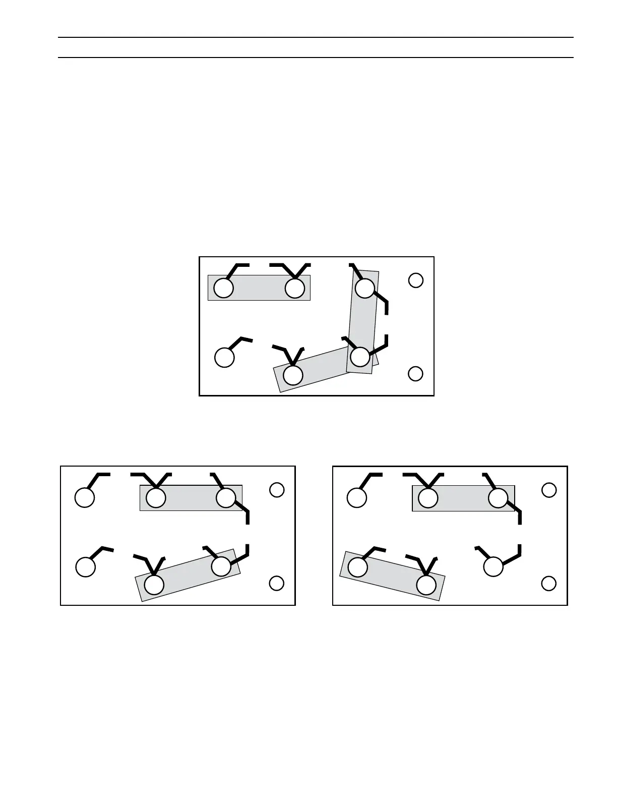
Figure 2-2. Input Terminal Board Conguration for 230V Input
Figure 2-4. Input Terminal Board Conguration for
575V Input
Figure 2-3. Input Terminal Board Conguration for
460V Input
5. Figures 2-2 thru 2-5 illustrate the input voltage ter
-
minal board and the input voltage link connections.
The particular voltages from which this power source
may be operated are stated on the rating plate. The
voltage links were factory set for highest voltage
stated on the rating plate. If the power source is to
be operated on another stated input voltage, the links
must be reset for that particular input voltage. Always
verify the input voltage and check the link arrange
-
ment regardless of factory setting. The voltage links
are set up by reconfiguring the copper link bars to
the voltage designations for the desired voltage.
SECTION 2 INSTALLATION
1
2
3
4
5
6
230
230
230/460
575
460/575
1
2
3
4
5
6
230
230
230/460
575
460/575
1
2
3
4
5
6
230
230
230/460
575
460/575
1
2
3
4
5
6
230
230
230/460
575
460/575
1
2
3
4
5
6
230
230
230/460
575
460/575
1
2
3
4
5
6
230
230
230/460
575
460/575
1
2
3
4
5
6
230
230
230/460
575
460/575
1
2
3
4
5
6
230
230
230/460
575
460/575
1
2
3
4
5
6
230
230
230/460
575
460/575
For 230 / 460 / 575V Models