24
NOTE: The power source also has 0 to 5 seconds preflow capability which is
factory set to zero seconds. If preflow is desired, locate R37 trim pot
on the Control PC board assembly mounted behind the front control
panel and then turn trim pot clockwise to desired position with a small
screwdriver.
I. Auxiliary 115-Volt Receptacle. This receptacle can be utilized to source
115-volt power for auxiliary equipment (grinder, coolant circulator, etc.)
and is protected by a 10-amp circuit breaker.
J. Arc Force Control (R5). This control is used in the STICK mode only. The
lower settings provide less short circuit current and a softer, more stable
arc. The higher settings provide more short circuit current and a forceful,
more penetrating arc. For most Stick welding, set the knob at 3 or 4 and
readjust up (forceful) or down (softer) as desired.
K. Balance Control (R4). This control changes the wave balance for Tig
welding operations (see Fig. 3-2). It is not operative in Stick welding opera
-
tions. With the dial set in its extreme counterclockwise or "Max. Cleaning"
position, the power source is set up for "balanced" wave operation (equal
portions of reverse and straight polarity - 50/50) for use in DC and AC Tig
with Maximum Cleaning (and minimum penetration). This will be the normal
(counterclockwise) position for most applications. As the potentiometer is
turned clockwise toward "Max. Penetration", cleaning action will lessen and
penetration will increase. This "unbalanced" wave output (more straight
than reverse polarity) should only be used for AC Tig applications when
needed.
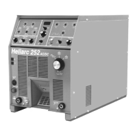
L. Volt/Amp Switch and Digital Meter (Optional on Heliarc 252). With
toggle switch in AMP position, digital meter will display preset current and
then actual current after the arc has been struck. With toggle switch in
VOLT switch, actual output voltage will always be displayed on the digital
meter.
M. Over Temperature Light. When this lights up, the power source has over
-
heated (exceeded duty cycle). The contactor will deenergize shutting
down all operations but the fan will continue to run. When the light goes
off, operations can be resumed.
N. 24V Circuit Breaker (CB1)
The 24V resettable circuit breaker (CB1) protects the solenoid valve and
torch trigger circuitry against overcurrent. (Section 5-2 provides trouble-
shooting information)
O. 115V Circuit Breaker (CB2)
The 115V resettable circuitry breaker (CB2) protects the 115 volt auxiliary
receptacle circuitry against overcurrent. (Section 5-2 provides troubleshoot-
ing information).
SECTION 3 OPERATION