5 OPERATION
0458 870 201
- 9 -
© ESAB AB 2014
5 OPERATION
General safety regulations for handling the equipment can be found in the "SAFETY"
chapter of this manual. Read it through before you start using the equipment!
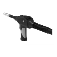
5.1 Contact tip
The hole size of the contact tip is determined by the diameter of the wire, the type of inert
gas and the level of current used. See the "Wear parts" chapter.
5.2 Wire liner
The spiral steel wire liner that comes as standard with the welding torch can be used for all
types of wire of the intended size with exception of aluminium.
PTFE-wire liners are suitable for welding with all types of wires (Al, Ss, and Fe).
However, it is recommended that PTFE-wire liners are not used when welding using Fe and
CW wires that are thicker than 1.2 mm due to the increased instance of wear.
PTFE-wire liners have a considerably shorter life than the standard steel spiral.
In order to ensure that you enjoy a satisfactory level of wire feed, select a wire liner in the
table in the "Wear parts" chapter.
5.3 Replacing the wire liner
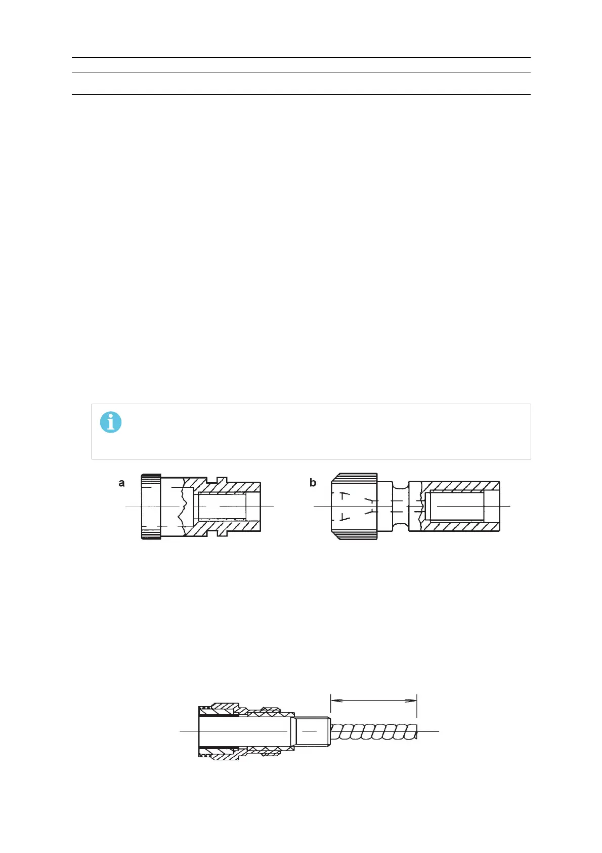
1. Fit the correct nipple.
NOTE!
Each wire guide is supplied with 2 nipples, 1 for ESAB connection and 1 for
EURO connection.
a) ESAB connection
b) EURO connection
2. Remove the gas nozzle and the tip adaptor.
3. Fit the wire liner in the hose package.
4. Cut the wire guide to the correct length using a projectile "X" as shown in the figure
below.
While cutting, the welding torch must be extended with the wire guide fully inserted into
the rear connector.
5. Remove sharp edges inside the liner after cutting.