E-IM54f P7/37
TD830
ELECTROSURGICAL UNIT
DUTY CYCLE
The duty cycle rating of 10 seconds ‘on’, 30 seconds ‘off’,
specified on the serial plate as 10s:40s, indicates that the
equipment can be used at full output power in any mode
for 10 seconds with a 30 seconds rest period. The unit
can remain connected to the mains electrical supply with
the mains switch in the ‘on’ position continuously. The ‘on’
period at lower power levels can be extended.
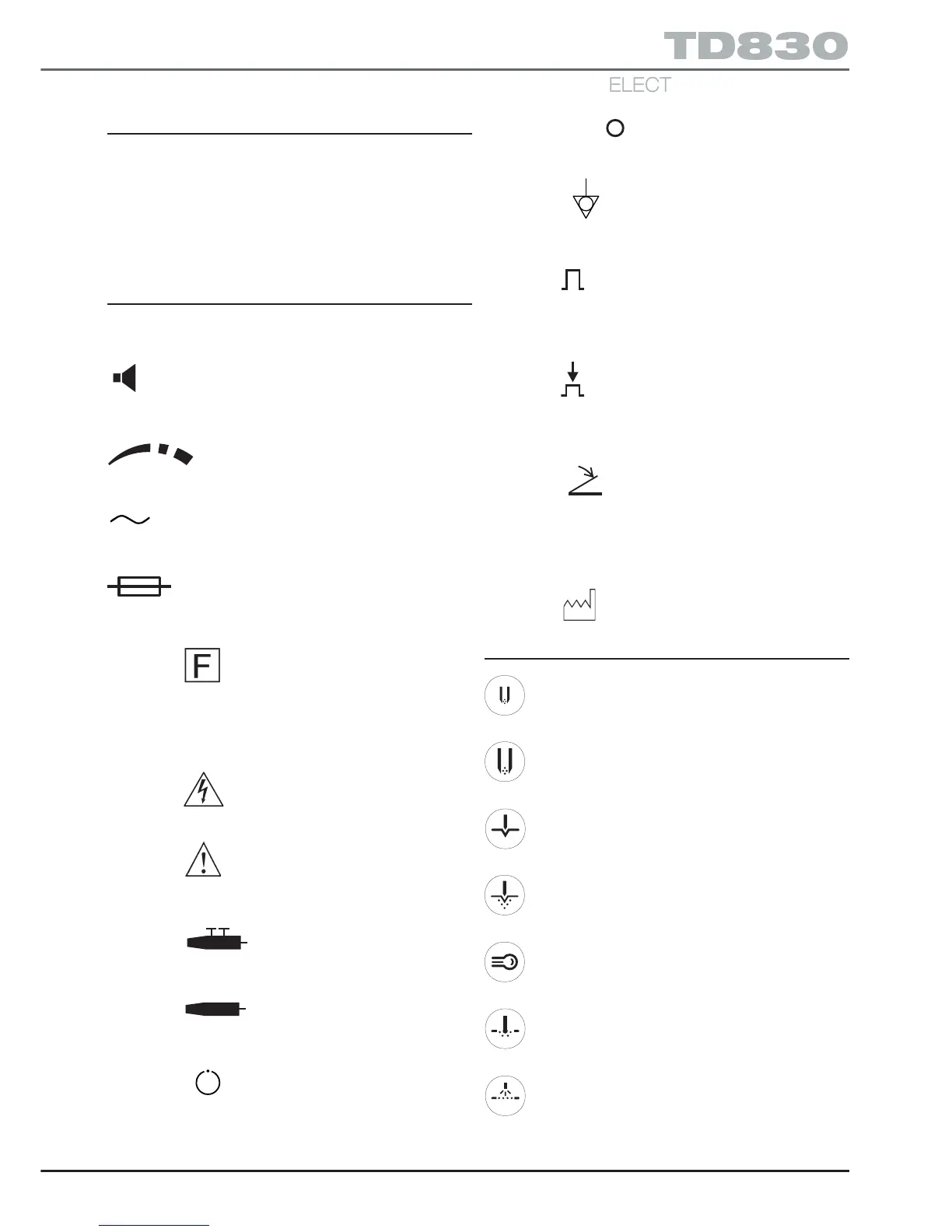
OTHER SYMBOLS
Note: For numbers in brackets refer to Illustration 11 which
folds out at the end of this manual.
This symbol above item (33) indicates the running
tone volume control which has a minimum sound level of
45dBA.
This symbol above items (1, 14, 21 and 33)
indicates increasing power output (1, 14 and 21) and
increasing volume (33) for running tone and ‘bleep’ volume.
This symbol on the rear panel serial plate (39) and
above the mains inlet (40) indicates that the equipment is
for use on alternating current only.
This symbol on the rear panel serial plate
indicates that the mains input fuses, rating and type, are
as shown below the symbol.
The symbol on the front panel denotes that the plate
electrode is isolated from earth at high frequency. (Note:
The plate electrode is also known as the dispersive, neutral,
return, indifferent or patient plate electrode and is often
simply called the ‘pad’).
The symbol on the front panel adjacent to the active
outputs (24 to 28) denotes dangerous voltages.
The symbol on the rear panel serial plate warns the
user to read the accompanying documents, the
‘Instructions for use’.
The symbol above sockets (25, 26, 27 and 28)
denotes connection socket for a two button electrode
handle (fingerswitch type).
The symbol adjacent to sockets (24, 26 and 31)
denotes connection socket for a non-switched active
handle actuated by a footswitch.
This symbol on the monopolar standby selection
button (32) (monopolar ‘on/off’ toggle button) indicates
standby mode for part of the equipment only.
The symbols I and adjacent to the mains ‘on/off’ switch
(42) indicate the ON and OFF positions respectively.
The symbol adjacent to item (34) indicates the
‘equipotentiality’ connection point. (Means for connection
of a potential equalization conductor).
The symbol adjacent to button (35) signifies the button
in the non-pressed (i.e. normal) state. (Digital display on
the front of the electrosurgical unit is a typical power figure,
e.g. 0-200watts for monopolar blend).
The symbol adjacent to button (35) signifies the button
in the pressed (i.e. activated) state. (Digital display on the
front of the electrosurgical unit shows a numerical value
up to 10).
The symbol adjacent to sockets (36, 37 and 38)
indicates the connection point for footswitches.
The symbol SN indicates serial number.
The symbol REF indicates catalogue number.
The symbol indicates date of manufacture.
BUTTON SYMBOLS
Press to select bipolar - micro range
Press to select bipolar - macro range
Press to select monopolar - cut
Press to select monopolar - blend
Press to select monopolar - specialist cut
Press to select monopolar - pinpoint coag.
Press to select monopolar - spray coag.