Page 7 of 13 0455-0322 Rev A
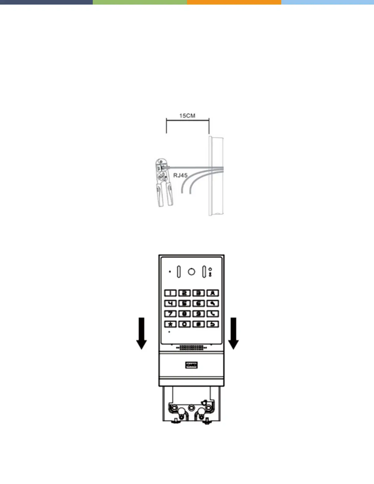
2. Pass all the wires through the silicone plug in the middle of the bottom case. All lines should be
reserved for 15~20CM length, as shown below.
Note: The outlet hole of the bottom case faces down
3. Connect the cables of RJ45, power, and electric-lock to the motherboard socket as mentioned in
connectors description (refer to Section 2).
4. Connect the terminal of the wired cable to the motherboard socket. Refer to wiring interface.
5. Test whether there is electricity by doing the following: Press the # button for 3 seconds to get the IP
address of intercom by voice. Input access password or press the indoor switch to verify that electric
lock functions.
6 Attach the device to the wall bracket in a top-down manner, locking the screws at the bottom, as
shown below.