Celebrating over 30 years of excellence in manufacturing ultrasonic cleaning
equipment, electropolishing equipment and associated chemistries
ESMA, Inc.
P. O. BOX 734 * SOUTH HOLLAND, IL 60473 * (800)-276-2466 * FAX (708)331-8919
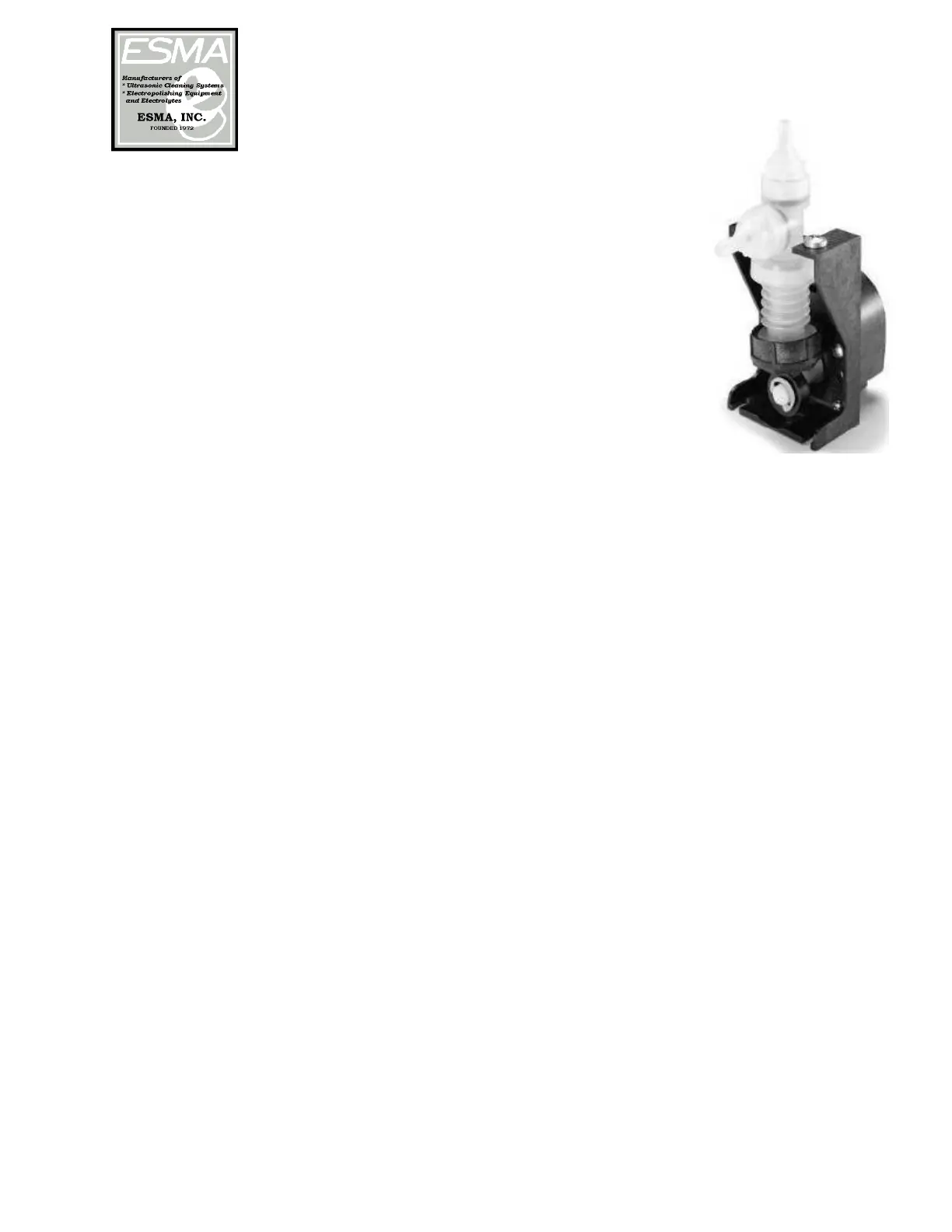
The Metering Pump is a Gorman-Rupp bellows metering pump.
The supplied inlet tube from the metering pump should be
inserted into a gallon jug of Esma cleaning solution concentrate.
The pump is configured to “meter” a 1% concentrate during the
fill cycle, approximately 180ml. Please use only proper detergent
which is formulated for use with the E789 model.
PLEASE READ THESE INSTRUCTIONS THOROUGHLY BEFORE
INSTALLATION AND OPERATION. CALL 800-276-2466 IF YOU
HAVE ANY QUESTIONS
2. INSTALLATION
If the control module is to be placed directly in front of tank, allow 5 inches
between counter opening and front of cabinet (diagram 1). Also, 28 inches of
clearance is necessary under the counter for drains.
Control Module - Cut opening of 4 ¼” x 10 ¼” in front of cabinet. The overall
flange of unit on front of cabinet is 5” x 12”, so center unit accordingly. Module
will be mounted later with 4, No. 8 wood screws.
Tank Module - Cut opening of 18” x 11 ¼” in top of counter. The overall flange
of unit on top of counter is 20” x 13”, so center unit accordingly. Place tank in
opening and mark on counter the mounting studs welded under top plate.
Remove tank and drill mounting holes with1/4” drill bit. Do not mount tank
until control module opening is cut out.
Tank Module should be set in counter first. A gasket is glued to the underside
of the top plate to prevent liquid from seeping into the counter. Place the tank-
mounting studs into the pre-drilled holes in counter and tighten down with 8 x
32 nuts and washers, which are supplied. (DO NOT OVERTIGHTEN).
Power Module measures 8’ x 16” x 18”D. However, 1” of clearance is necessary
both at the front and back of unit for proper ventilation. The electrical
connections, from tank and control modules, attached to the top of the module,
require additional 2 to 3 inches of space.
The Metering Pump should be monitored to assure that there is solution in
the jug. Due to the length of tubing, it will take one cycle for the metering
pump to become “primed”. Once the pump is primed, a 1% solution
concentrate will automatically be added to the water during the fill cycle.
Please regularly check to make sure that there is adequate cleaning solution in
the jug.