5
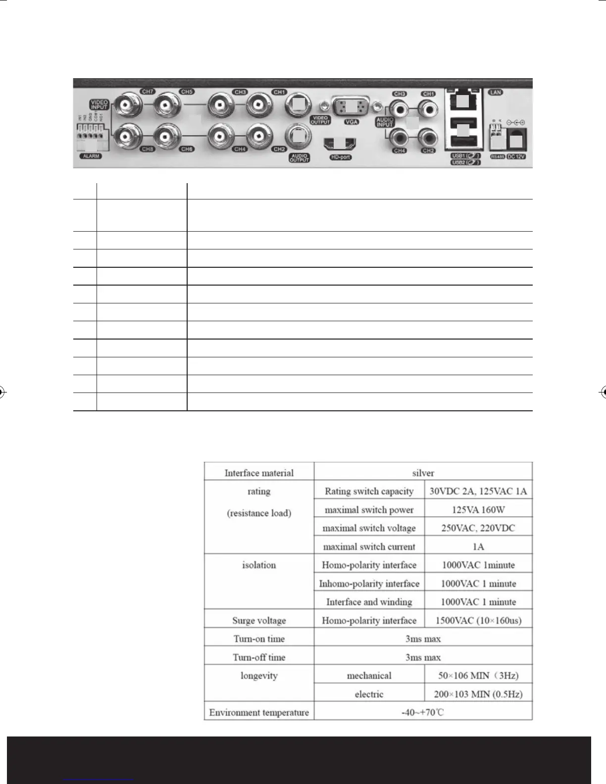
No. interface ID Description
1 ALARM Switch alarm output (normally open contact)
INPUT/OUTPUT External devices require a power supply
2 VIDEO-IN Video input BNC connectors x 8
3 VIDEO-OUT Video output BNC
4 AUDIO-OUT Audio output AV
5 VGA VGA display output
6 HDMI HDMI display output
7 AUDIO-IN Audio input AV x 4
8 NET/LAN Network Interface
9 USB USB interface x 2
10 RS485 RS485 Interface
11 DC-12V 12V Power Input from power supply
NB. To obtain the best quality on screen display it is highly recommended to
connect a monitor via the HDMI output.
In order to avoid
damage when using
the alarm inputs/
outputs please refer
to relay parameter list:
Rear Panel
1
2
4
6
7
10 11
9
8
3
5
DVR8iP Digiview8iPro Manual_Layout 2 12/03/2014 09:33 Page 5