1 Overview
The module has 11 pins. See pin definitions in Table 2.
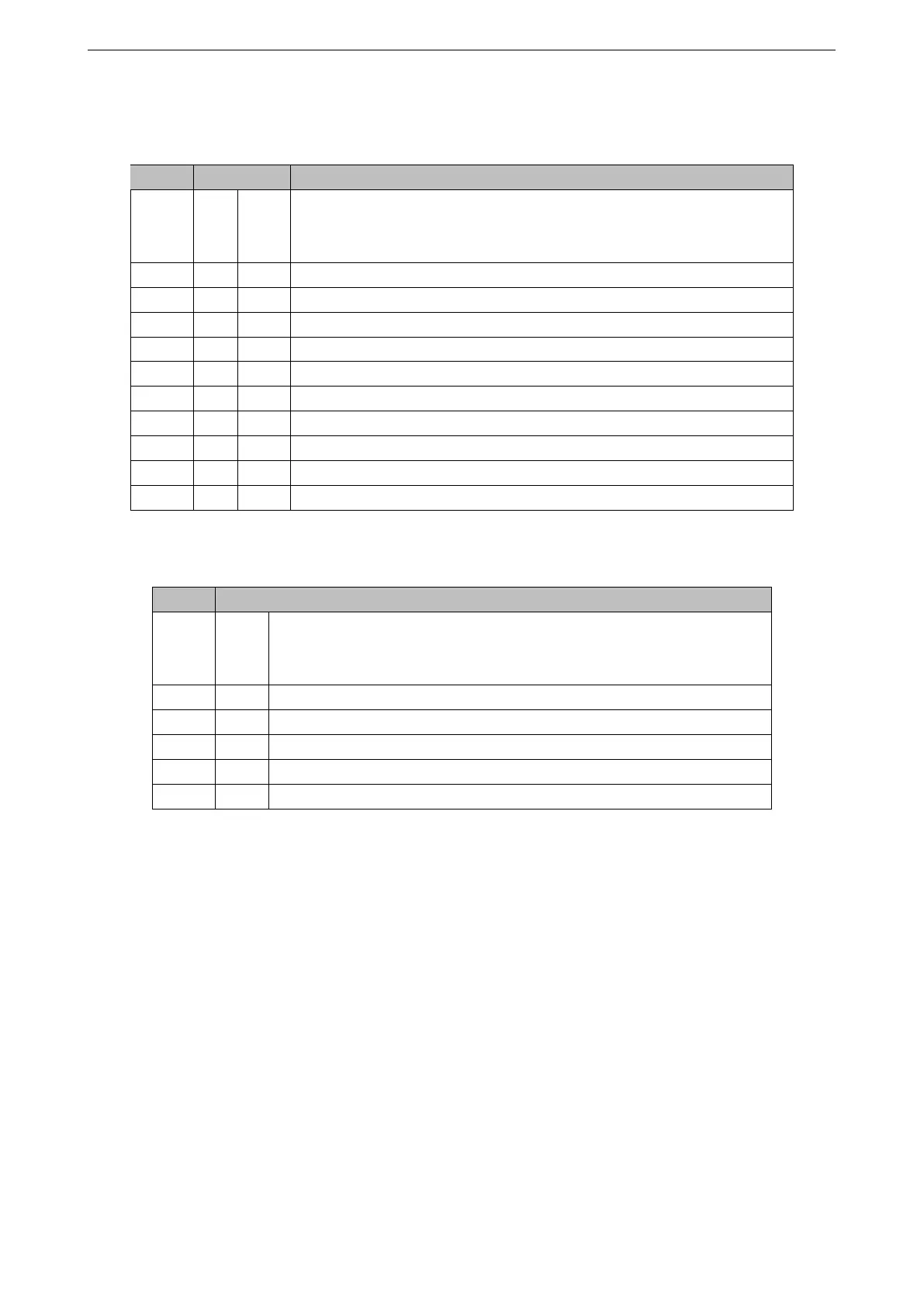
Table 2: Pin Definitions
Name No. Type
1
Function
EN 1 I
High: on, enables the chip.
Low: off, the chip powers off.
Default: internally pulled-up
IO1 2 I/O/T GPIO1, ADC1_CH1, XTAL_32K_N
IO6 3 I/O/T GPIO6, FSPICLK, MTCK, LED PWM
IO7 4 I/O/T GPIO7, FSPID, MTDO, LED PWM
IO3 5 I/O/T GPIO3, ADC1_CH3, LED PWM
3V3 6 P Power supply
GND 7 P Ground
RX 8 I/O/T GPIO20, U0RXD
TX 9 I/O/T GPIO21, U0TXD
IO5 10 I/O/T GPIO5, ADC2_CH0, FSPIWP, MTDI, LED PWM
IO4 11 I/O/T GPIO4, ADC1_CH4, FSPIHD, MTMS, LED PWM
Table 3: Test Point Definitions
Name Type
1
Function
EN I
High: on, enables the chip.
Low: off, the chip powers off.
Default: internally pulled-up
TX I/O/T GPIO21, U0TXD
RX I/O/T GPIO20, U0RXD
GND P Ground
3V3 P Power supply
IO9 I/O/T GPIO9
1
P: power supply; I: input; O: output; T: high impedance.
Espressif Systems 5 ESP8685-WROOM-03 User Manual v0.1
 Loading...


