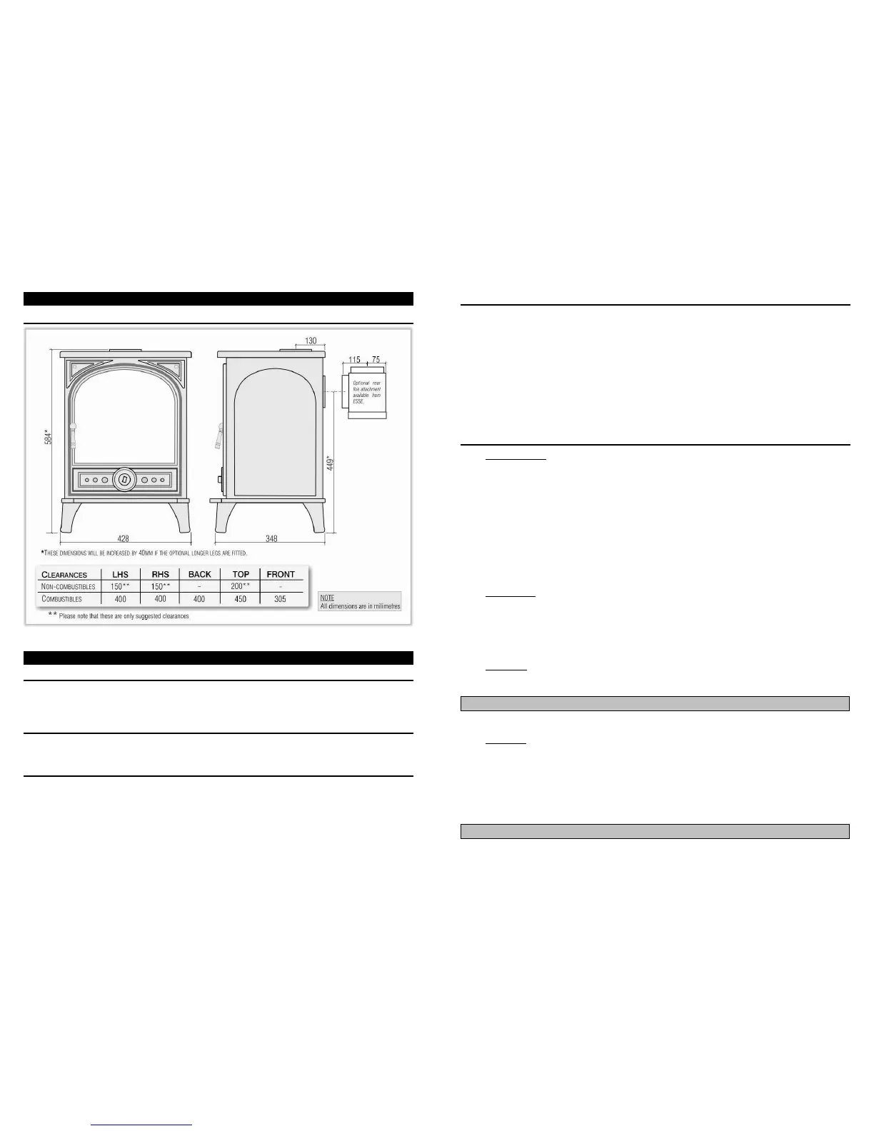
The overall dimensions of the stove are shown in Fig.3. Fig.3 shows recommended distances between the stove and
surrounding combustible materials. As a rule, any surrounding combustible material should not exceed 80ºC. There
should be sufficient space around the stove for service work.
The construction of the hearth must conform to Building Regulations, must be firm, non-combustible and capable of
supporting the stove.
The flue pipe used to connect the stove to the chimney is 125mm (5'') in diameter. The stove supplied is ready for
top flue connection. The flue blanking plug supplied with the stove is used to block the rear flue outlet. To change to
rear connection the flue blanking plug can be moved to the top outlet. To access the bolts attaching the rear flue
connection, the fuel bar and the baffle must be removed (Fig.7-8) A rear flue box attachment, available from ESSE
or http://esseparts.com, allows the stove to be installed further out of any building recess. Fig.1 shows suitable flue
connections.
DIMENSIONS & CLEARANCES
1. The installation must allow for adequate chimney sweeping.
2. Avoid using bends greater than 45ºC to the vertical. All pipe flue sections should be as close to vertical as
possible.
3. All joints in the flue system must be effectively sealed.
4. All flue sockets must face upwards.
On completing the installation, check that all the internal components of the stove are positioned correctly.
Wood Burning parts: Check – Base plates, baffle, side and back bricks. See Fig.5-8.
Mineral Fuel Burning parts: Check – Grate bars, baffle, side and back bricks, fuel bar. See Fig.6.
• T
HE
B
ASE
P
LATES
The base plates are available from your ESSE dealer as an optional extra and must be used if the stove is
operated in wood burning mode. See Fig.5. The base plates are not necessary when the stove is used in mineral
fuel burning mode. Baffle, fuelbar, bricks, grate bars, grate rest and riddle bar have to be removed before the
base plates can be positioned. Position the plates in the following order:
1. Rear base plate;
2. Side base plates;
3. Bottom base plate.
Remove in the reverse order.
• T
HE
F
UEL
B
AR
1. Position the fuel bar as shown in Fig.7. Place the right of the fuel bar onto the right hand side brick rest.
2. Lower the left of the fuel bar down onto the left hand side brick rest.
Remove in the reverse order.
• T
HE
B
AFFLE
Position the baffle as shown in Fig.8.
• T
HE
B
RICKS
The bricks can be removed in the following order
1. Both back bricks;
2. The right hand side brick;
3. The left hand side brick (the left brick and the riddle bar are removed at the same time as shown in Fig.9).
Replace the bricks in reverse order.
Note: The fuel bar and grate bars need to be removed when placing or removing the baffle.
Note: The fuel bar and grate bars and baffle need to be removed before replacing the baffle.