72 www.eta.co.at
[Heating pipeline] function block ETAtouch controller
6.10 [Heating pipeline] function block
Overview of heating pipeline
A heating pipeline is defined as a connection between
a heat producer and a consumer with an additional
pump and optional mixing valve.
Example: Boiler and consumer are in different and
widely separated buildings.
The heat is supplied to the connected consumers
(buffer, heating circuits, hot water tank, etc.) via the
heating pipeline with the heating pipeline pump.
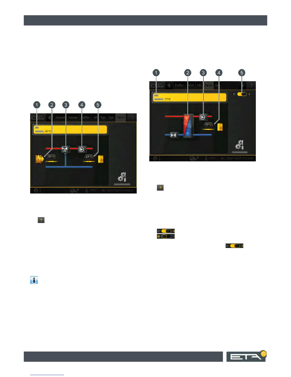
Fig. 6-64: Heating pipeline with mixer
1 Operating condition and information.
A description of the operating conditions can be
found in the integrated Help menu by pressing the
button.
2 Producer for the heating pipeline.
Currently the heat producer provides a 77 °C flow
temperature in the pipeline.
3 Pipeline mixer
4 Pipeline pump
5 Heating pipeline consumers
Currently, the consumers are charged at a flow
temperature of 47 °C.
To protect the consumers, an antifreeze function
is available in the pipeline pump control system.
If the outside temperature drops below the set frost
protection limit (factory set at -20 °C), the remote pump
remains in operation until the outdoor temperature is at
least 2 °C higher than the set temperature [Frost pro-
tection].
Transmission line as heat transfer station
With the [Transfer station] option, this function block
can be used to control a heat transfer station in a local
heating network. This function block is then the heat
producer for the connected consumers such as
heating circuits, buffers, hot water tanks, etc.
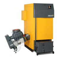
Fig. 6-65: Transmission line as heat transfer station
1 Operating condition and information.
A description of the operating conditions can be
found in the integrated Help menu by pressing the
button.
2 Heat transfer station heat exchanger
3 Heating pipeline pump
4 Heat transfer station consumers.
Currently, the consumers are charged at a flow
temperature of 77 °C.
5 On/Off switch for the heat transfer station
= switched on
= switched off
If the heat transfer station is turned on ( ), then
the connected consumers can be supplied with heat.
Once the heat is delivered to the consumer, a yellow
line appears beside the flow temperature and the
symbol of the consumer in the overview.