74 www.eta.co.at
Function block [special conveyor] and [external conveyor] ETAtouch controller
6.11 Function block [special
conveyor] and [external
conveyor]
Special types of conveying systems
This function block is used with wood chip boilers to
control special versions of fuel conveyor systems. For
example:
• Silo conveyor system
• Double agitator (two agitators supply one boiler)
• Intermediate conveyor screw (several conveyor
screws in series)
Conveyors with a drive power up to 1.1 kW are
controlled in the [Special conveyor] ([SpConv])
function block. This covers all ETA conveyors.
Conveyors with a higher drive power are controlled in
the [Ext. conveyor] ([ExtConv]) function block.
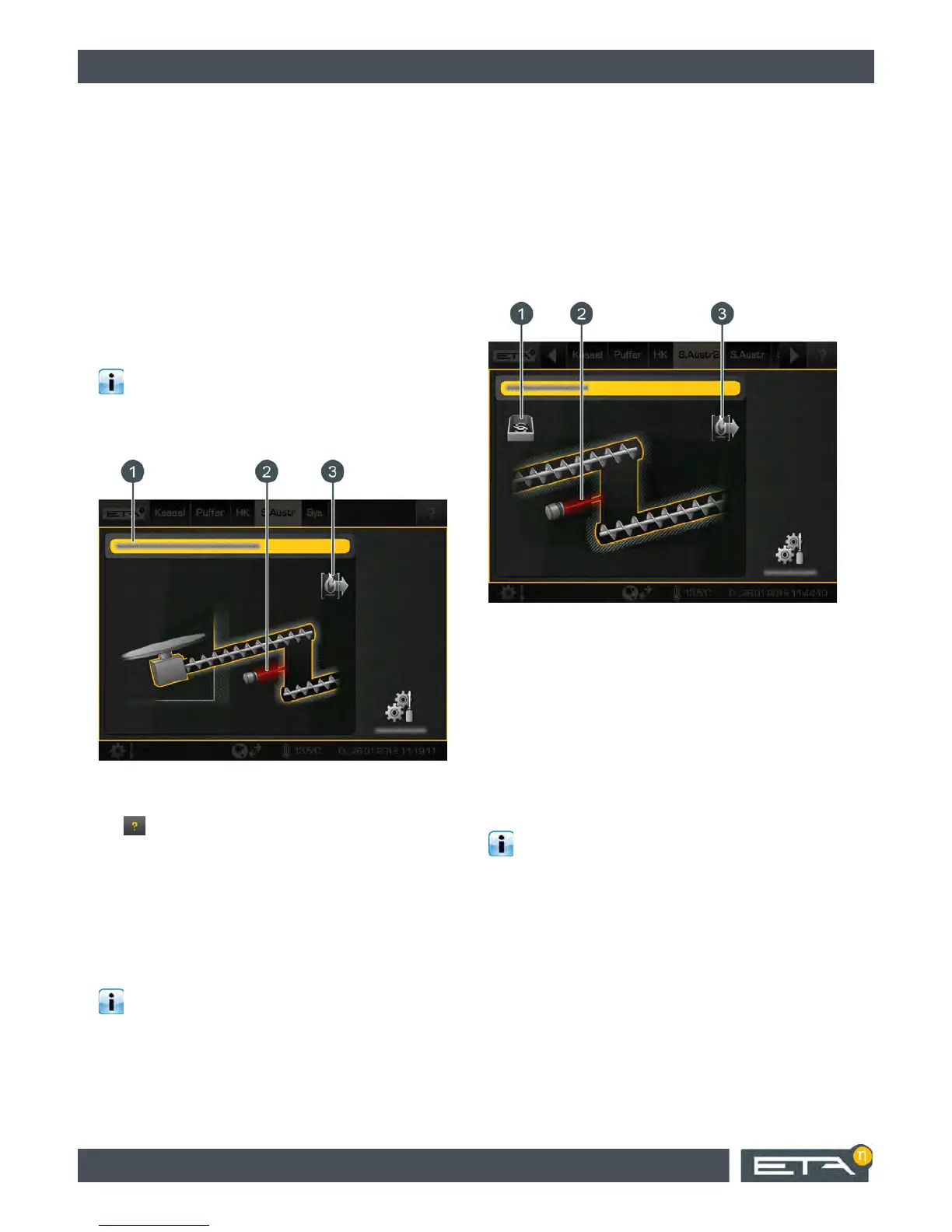
1 Operating condition and information.
A description of the operating conditions can be
found in the integrated Help menu by pressing the
button.
2 Light barrier (only with [Light barrier in drop chute]
option)
3 Consumers of the conveying system (the boiler)
The agitator and the screw are shown in green as soon
as they begin to transport fuel. They are displayed in
grey when not in operation or when the screw is turning
in reverse in order to remove a blockage.
A light barrier for the drop chute is supplied ex-
works for controlling the fuel conveying system.
For external conveying systems, the light beam is
available as an option.
If the drop chute is filled with enough fuel, the light
barrier is interrupted and displayed in red. If the light
barrier is displayed in green, there is no fuel or insuffi-
cient fuel in the drop chute.
6.11.1 Intermediate conveyor screw
Intermediate conveyor screw overview
When several conveyor screws in series are used to
transport fuel to the boiler, they are referred to as inter-
mediate conveyor screws.
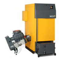
1 Producer for the intermediate conveyor screw
(conveying system)
2 Consumer of the intermediate conveyor screw
(boiler)
3 Light barrier (only with [Light barrier in drop chute]
option)
The intermediate conveyor screw appears green when
it is turning in the discharge direction. The intermediate
conveyor screw is shown in grey when not in operation
or if it is turning against the discharge direction in order
to remove a blockage.
A light barrier is also supplied with the intermedi-
ate conveyor screw ex-works for controlling the
fuel transport. For external conveying systems, the
light beam is available as an option.
If the drop chute is filled with enough fuel, the light
barrier is interrupted and displayed in red. If the light
barrier is displayed in green, there is no fuel or insuffi-
cient fuel in the drop chute.
6.11.2 Double agitator
Double agitator overview
When two agitators transport the fuel to a discharge
screw and from there to the boiler, the configuration is
called a double agitator. Each agitator is shown in its
own function block.