8 CEM+ Sensor Rack Retrofit Manual
d: Use a 3/8” socket to re-install the B phase bar with the five bolts.
e: Re-attach the red sense wire to the B phase bar with the previously used screw.
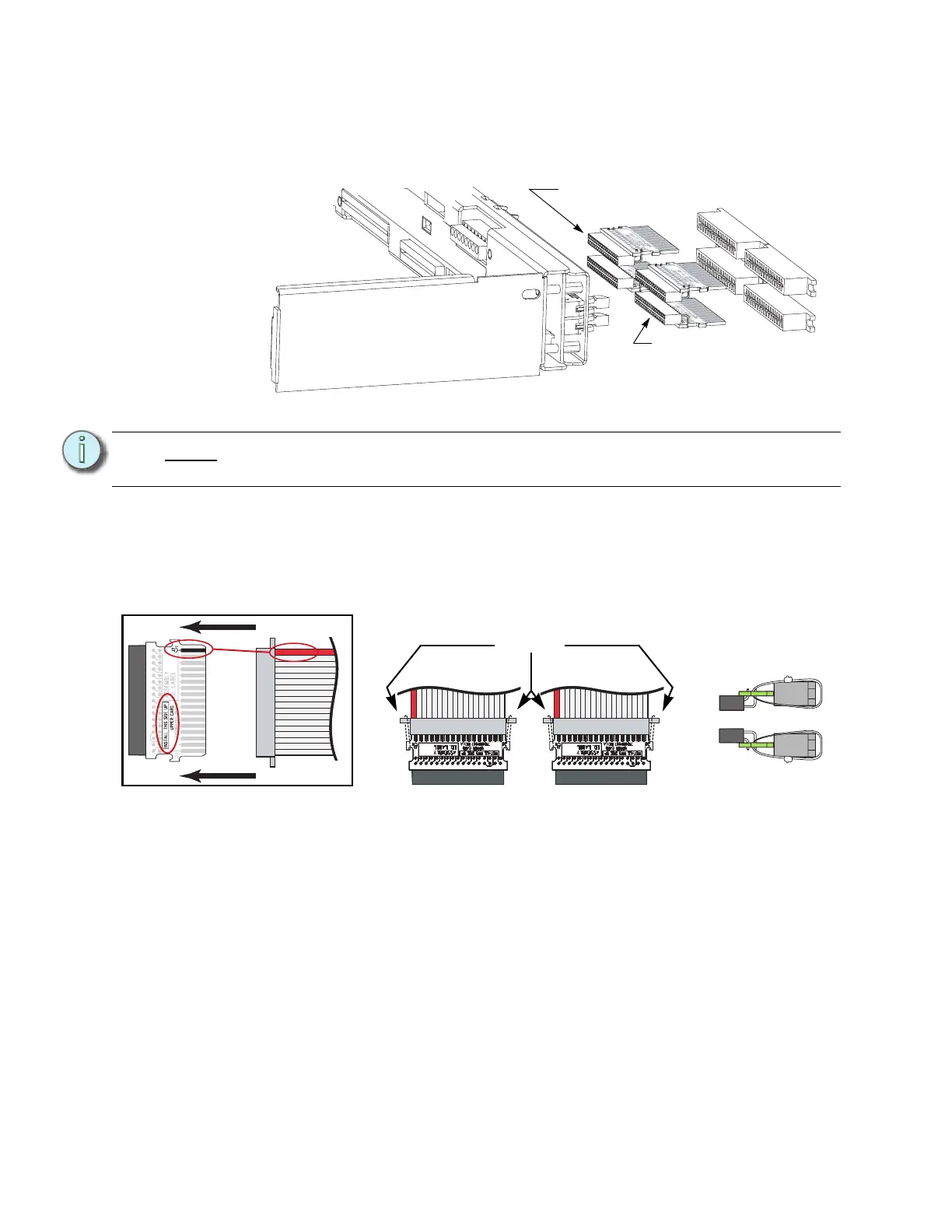
Step 9: Identify the different dimmer output ribbon cable transition cards. An SR6 and
SR12 will only have a single “lower” card.
Step 10: Mate the transition cards with the ribbon cable edge connectors as indicated
below. Secure the ribbon cable connectors to the transition cards with wire ties.
The tie wrap binding needs to be on the top for an Upper board and on the
bottom for a Lower board for clearance. Clip wire tie ends for neatness.
Step 11: Terminate the Ethernet cable with the provided Ethernet Termination Kit (ETC
Part# 4101A2003). Follow the wire preparation and termination instructions
included with the kit.
Note:
There are two different types. An “upper” card and a “lower” card. The PCB card
is marked for both the type and which side is up when installed.
1
3
4
2
This is an “Upper”
transition board
(7150B5007)
This is an “Lower”
transition board
(7150B5006)
Match
the red
wire to
pin-1
and be
sure the
proper
side is
up
Wire tie the
connectors
together
Position of the
tie wraps
On top for Upper
On bottom for Lower