2 The Retrofit 7
Step 5: Install the power adapter harness to edge connector (straight thru PCB) to old
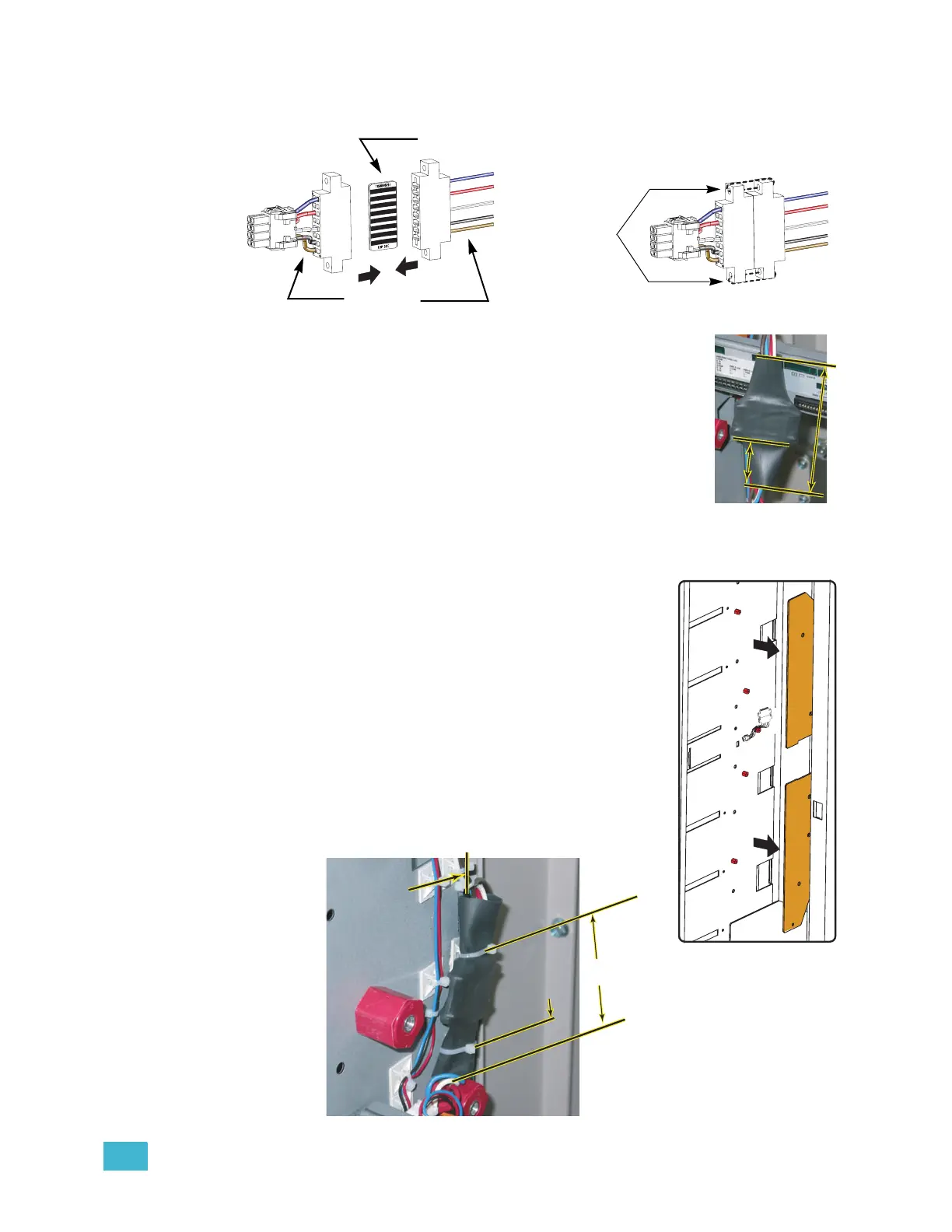
power connector (match the wire colors)
.
Step 6: Secure the power connectors together with provided 4"-
wire-ties. Clip wire tie ends for neatness.
Step 7: Center the provided 4 1/2” x 1/2” dia. heat shrink tubing over
the power harness connectors (leaving at least 1 1/4” past
each connector) and heat shrink it with a heat shrink gun.
Step 8: Secure the power harness to the rack:
• SR6, SR12 & SR24 racks
a: Use a pair of sticky-back tie mounts and wire ties to secure
the power harness to the rear or left side of the rack. The
new power connector should be facing out of the rack (near where the old
harness used to be installed) and the power harness needs to be kept back
from the phase bars.
• SR48 racks only.
a: Remove the screw near the bottom of B phase bar
that connects the red sense wire to the phase bar.
b: Use a 3/8” socket to remove the five bolts holding the
B phase bar in place and push the phase bar towards
the center of the rack. You only need enough room
to mount the power harness. Do not remove the
power feeder.
c: Using a couple sticky-back tie-mounts, mount the
power harness to the left side of the rack (see detail
below). The new power connector should be facing
out of the rack (near where the old harness used to
be installed) and the power harness needs to be kept
back from the phase bars.
O
h
,
I
w
ish I
w
e
r
e
a
n Oscar
M
e
y
e
r
® w
iene
r
..
.
Wire-tie the
connectors
together
The PCB is the same on
both sides, top and bottom.
Match the
wire colors
1-1/4"
Min.
1-1/4"
Min.
4 1/2"
4 1/2"
1/2"
1/2"
Mount next to
edge of sheetmetal
Mount next to
edge of sheetmetal
Place the first tie-wrap mount
Place the first tie-wrap mount
1/2" above the middle Glastic.
1/2" above the middle Glastic.
3"
3"
Place the first tie-wrap mount
1/2" above the middle Glastic.