R
(ρ=2πaR
a:1 m-100m,
π=3.14)
Note: 1. When rC max or rP max, additional error≤±3%rdg±5dgt.
(rC max: 4kΩ+100R<50kΩ, rP max: 4kΩ+100R<50kΩ)
2. When 5V interference voltage, additional error≤±5%rdg±5dgt.
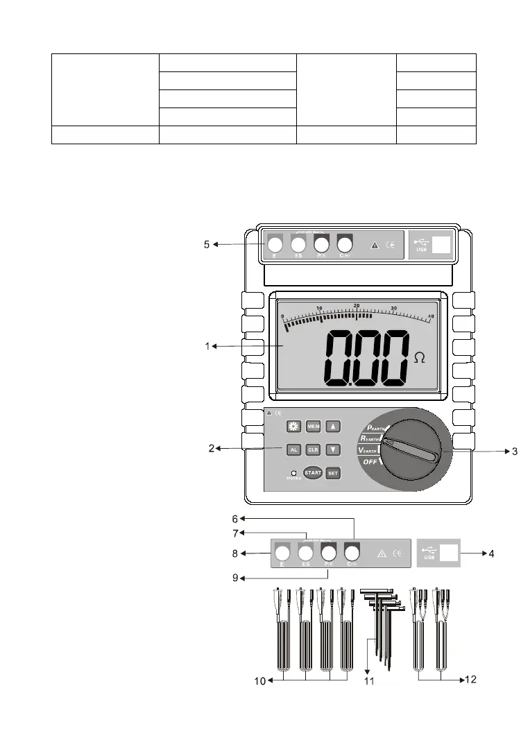
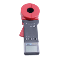
III. Tester Structure
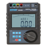
1. LCD
2. Button area
3. Rotary switch
for selecting function
4. USB Interface
5. Interface of
testing wires
6. C(H) interface:
Current electrode
7. ES interface:
Auxiliary earth electrode
8. E interface:
Earth electrode
9. P(S) interface:
Voltage electrode
10. Standard test wires
11. Auxiliary grounding rod
12. Simple test line