2 Mechanical and electrical installation
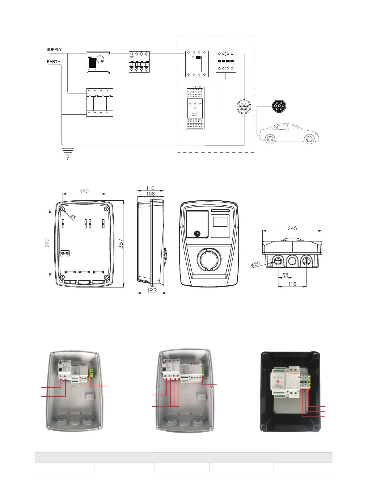
2.1 Internal structure drawing
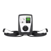
2.2 Installation
A、Overall dimension and installation size
B、 Drill 4xø6 35mm counterbore holes on the wall with the size of the mounting holes, insert the expansion screw plastic tube,
and then screw in the M4x30 self-tapping screws from the internal mounting holes of the charging pile.
C、The power cord is connected to a type B leakage circuit breaker, the single-phase charging pile is connected to N and L, and
the three-phase charging pile is connected to N\L1\L2\L3,
The ground wire (PE wire) is connected to the yellow and green two-color terminals, the schematic diagram is as follows:
Recommended cable section:
PE
EKEC4EKEC1-1 EKEC1-3
PE
PE
N
L1
L2
L3
L
EKEC1
Current value(A) 10 16 20 32
Wire area(mm
2
) 2.5 2.5 4 6
Digital E Meter
Surge Arrester
Type2
BLU(N/C) GRE(CHG)
Current adjustment
RED(ERR)
PLUG
MCB RCCB(Type B)
16/32A
Contactor
-05-
L
N
N
 Loading...