25
10• MAINTENANCE
Your mower is tted with a maintenance counter (page 9). This is a
useful tool that will inform you on the servicing cycles of your mower.
It displays the hours of use remaining until the next service is due. A
service is indicated by the ashing of the hours and:
- one spanner for the 1st service or an intermediate service.
- 2 spanners for a complete service.
Each time the engine is switched on.
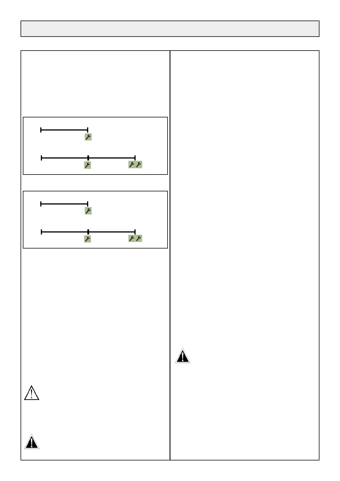
BPHP2 - BPHPX2
First service
20hrs 0hrs
Intermediate service Complete service
250hrs 125hrs 0hrs
HVHP - HVHPX - BVHP - BVHPX
First service
10hrs 0hrs
Intermediate service Complete service
200hrs 100hrs 0hrs
REMARKS:
- If you do not have the tools or skills necessary, please contact your
dealer.
- It is strongly recommended that you strictly respect the service fre-
quencies.
After re-initialising at 0hrs, the spanner(s) stop ashing and the counter
displays 250hrs for diesel engine mowers and 200hrs for petrol engine
mowers.
After re-initialising at 125hrs for diesel engine mowers and 100hrs
for petrol engine mowers, spanner(s) stop ashing and the countdown
continues.
RE-INITIALIZATION:
after each service, remove the connector
(a picture 20) and connect the other connector (b) for a few seconds. To
do this, unscrew the plastic nuts (c) on the comfort counter and take it
out through the top of the console.
CAUTION: If the intermediate service has not been done
before the counter displays 62.5 hrs, do the complete service
immediately. In this case after re-initialization, the counter
will return to 250 hrs for diesel engine mowers and 200h
for petrol engine mowers. After re-initialization, reconnect
connector (a picture 20). If you do not, the indicator lights
and counters will no longer work.
LIFTING YOUR MACHINE
If you need to carry out some work underneath the machine
that requires raising it off the ground, we recommend the use
of a lift table able to take the weight of your machine.
10•1 ENGINE MAINTENANCE
10•1•1 CHECK THE ENGINE OIL LEVEL (each
time you use the machine)
• Place the mower on a horizontal surface.
• Open the engine hood and the intake pipe (paragraph 9•1 - page 23).
• Clean around the dipstick opening.
• Remove the dipstick: a picture 21a for Perkins motor - a picture 21b
for Briggs & Stratton motor.
• The oil level must be kept between [MINI] and [MAXI] at all times.
If necessary, top up with diesel engine oil 15W40 (BPHP2, BPHPX2)
ref. ETESIA 29591 (2l can), or with 10W40 grade oil (HVHP, HVHPX,
BVHP and BVHPX) ref. ETESIA 38383 (2l can). Do not ll above the
[MAXI].
10•1•2 ENGINE OIL CHANGE
BPHP2 AND BPHPX2
After the initial 20-hour service, the oil must be changed every 500
hours or at least once a year.
HVHP, HVHPX, BVHP AND BVHPX
After the initial 10-hour service, the oil must be changed every 100
hours or at least once a year.
• Run the engine to heat up the oil.
• Place the machine on a horizontal surface.
• Stop the engine, remove the ignition key. Wear gloves.
• Place a sufciently large recipient underneath the engine drain screw
(a picture 22).
• Unscrew the screw or the drain tap and let the used oil run out into
the recipient.
• Clean and screw back the screw or the drain tap.
• Clean around the ller hole to avoid any impurities getting into the
engine.
• Slowly pour in the new fuel engine oil (capacity: see technical
characteristics) - For models BPHP2 and BPHPX2 Etesia
recommends SHELL Rimula X 15W40 (ref. 29591), and for HVHP,
HVHPX, BVHP and BVHPX ETESIA recommends 10W40 grade
oil (ref. 38383).
• Check the oil level using the dipstick. The level must reach the [MAXI]
mark without going over it.
CAUTION! Take great care when emptying hot oil. Never
touch the exhaust pipe, the cylinders or the rocker cover as
you could burn yourself.
• Check that the drain screw is tight and there are no leaks and close
the engine cover.
• Take the used oil to an approved collection point.
10•1•3 CHANGE THE ENGINE OIL FILTER
• Change lters during each engine oil change.
PERKINS MOTOR
• Open the engine hood, remove the engine cooling radiator inspection
trap and open the right hand side cover and the suction duct (a picture
23a) for access to the lter (b).