messtechnik gmbh
13
7.1 Wiring instructions
Electrical and magnetic fields often disturb the measurement circuit. These dis-
turbances typically emanate from power lines running parallel to the test cables,
but they can also come from nearby contactors or electric motors. Interference
or noise voltages can be injected into the circuit as well electrically, especially if
the measurement chain is grounded at many points. This can give rise to potenti-
al differences.
Please note the following instructions.
• Use only shielded, and low-capacitance cables.
• Connect the supply voltage correctly
• Do not lay the device cable parallel to heavy-duty or control lines.
• Avoid leakage fields from transformers, motors and contactors.
• Do not ground the transducer, analyzer and indicating unit
at multiple points.
Connect all devices in the measurement chain to the same
protective conductor.
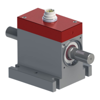
7.2 Connectors
The transducers are fitted with a 12-pin integrated connector Binder model 680.
 Loading...