messtechnik gmbh
15
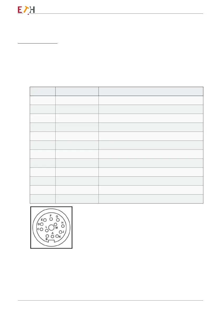
8. Pin assignment
8.1 DRVL standard cable
AK12.4 for active sensors
12-pin connector
(Top view of transducer connector)
External EMC circuit
A 100 nF / 50 V ceramic capacitor can be soldered between pins C - D at the
analyzer to suppress conductor-borne disturbances.
PIN D (torque ground) and PIN E (power supply ground) are electrically isolated
internally, short at the power source if required (not at the transducer).
Pin Colour Occupancy DRVL
A Green Frequency output
B Red / Blue Angle exit track B = 90 °
C Yellow Moment exit
D White Moment mass
E Grey Supply + angle / speed ground
F Pink Supply + 9… 28V
G Grey / Pink Speed / angle output track A = 0 °
H Purple Memory chip
J Black Message ready for operation
K Red Control entrance
L Brown Inverted frequency output
M Blue Voltage reference angle signal
 Loading...