10.7 Model Memory
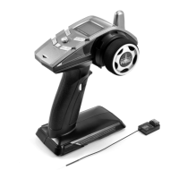
The transmitter has 6 different memories to allow it to be used with multiple mod-
els. Each memory has an individual bind to a receiver, so please follow the binding
processwhencreatinganewprole.Ifyouneedtopurchaseextrareceiverstousein
different models, the part number is ET1153.
10.8 Fail Safe
WhenthisisswitchedonthereceiverwillreturnthethrottleservoorESCtoit’spre-
set position in the event that there is a loss of signal between the transmitter and
receiver.
To set the failsafe position, highlight the ‘Set’ indicator in the menu, them move the
throttle trigger to the desired position and press the ‘Enter’ button on the transmitter.
Release the throttle trigger to the neutral position and the word ‘Successful’ on screen
will indicate the position has been stored.
Weadviseasettingof50%brakeforfuelpoweredmodels,andneutralforelectric
models.
Please note that the failsafe requires battery power to the receiver in order to operate. If
the battery connection to the receiver fails, or the voltage supply to the receiver is too low
then the failsafe will not operate!
10.9 Multi Option
10.9.1 Sound
This setting will mute any tones from the transmitter when set to ‘off’. Please note
that this will also affect any alarms or timers that are set.
10.9.2 Throttle Hold
Thisisalsosometimesreferredtoas‘IdleUp’andcanbeusefulwhenstartinganitro
engine.WhentheThrottleHoldisactiveapplyingthethrottleandreturningthetrigger
toneutralwillleaveapartialthrottleapplication.WhentheThrottleHoldvalueisset
to 100% then this will provide a 40% throttle opening when the trigger is returned to
it’s neutral point. The setting is linear, so a 75% setting will achieve 30% throttle open-
ing, a 50% setting 20% throttle opening and 25% setting 10% throttle opening. Apply-
ing the brakes and returning the throttle trigger to it’s neutral position will allow the
throttleopeningtoresettozero.Wedonotadvisethatthissettingbeturnedonwhilst
driving a model, and that it only be used to aid engine starting and warm up.
10.9.3 Channel Mix
This allows a second servo or ESC to be connected to Channel 3 of the receiver, and it
will follow the movement of Channel 2. The direction of travel of the devices con-
nected to Channels 2 and 3 can be set independently of one another in the Channel
Reverse sub menu.
8

 Loading...