8
Operating Instructions
Evaluation Unit CMS-E-ER
Technical data
Parameter Value Unit
Housing material Polyamide PA6.6
Dimensions 114 x 99 x 22.5 mm
Weight 0.22 kg
Ambient temperature 0 … +55 °C
Storage temperature -25 … +70 °C
Degree of protection Terminals IP20 / housing IP40
Degree of contamination
(external, acc. to EN60947-1)
2
Mounting Mounting rail 35mm acc. to DINEN60715 TH35
Number of read heads 1 … 30 read heads with reed contacts,
1 … 10 read heads with Hall sensors
Connection Connection terminals
Operating voltage U
B
24 ±10% V AC/DC
Internal fuse
(operating voltage U
B
)
750 (automatically resetting fuse PTC) mA
Safety contacts 2 NO contacts
Auxiliary contact 1 NC contact
Switching voltage U
max.
240 V AC
Current consumption at DC 24 V 10 … 110 mA
Switching current I
max.
at 24 V 3 A
Switching current I
min.
at 24 V 10 mA
Breaking capacity P
max.
720 VA
External contact fuse
(safety circuit) acc. to EN60269-1
4 A gG
Switching current I
max.
at DC 24 V 1.5 A
Utilization category I
e
1)
U
e
1)
acc. to EN60947-5-1 AC-1 3 A 230 V
AC-1 3 A 24 V
AC-15 0.9 A 240 V
AC-15 0.9 A 24 V
DC-13 1.5 A 24 V
Switching load acc. to UL Class 2
Input: 24 V AC/DC
Output: 30 V AC
24 V DC
Rated insulation voltage U
i
250 V
Vibration resistance Acc. to EN60947-5-2
Mechanical operating cycles, relay 10
7
EMC compliance Acc. to EN60947-5-3
Approval TÜV, UL
LED displays See drawing
Risk time acc. to EN60947-5-3 20 ms
Reliability values acc. to ENISO13849-1
As a function of the switching current
at 24 V DC
≤ 0.1 ≤ 1 A
Number of switching cycles/year < 166,000 < 70,000
Mission time 20 years
Category
1 read head 4
>1 read head 3
Performance Level (PL)
1 read head e
>1 read head d
2)
PFH
D
1 read head 2.5 x 10
--8
>1 read head 1.0 x 10
-7
2)
1) I
e
= max. switching current per contact, U
e
= switching voltage
2) This value applies to cables laid with protection.
The following applies if cables are laid without protection and more than one door must be opened
frequently or if cables are laid without protection and more than 5 doors are connected in series:
Performance Level = PLc, PFH
D
= 1.1
-6
.
On this topic, also see ENISO14119:2014, section 8.6, and ISOTR24119.
Evaluation of the diagnostic coverage according to ISOTR24119 must result in at least the value
low
in order to achieve PLd.
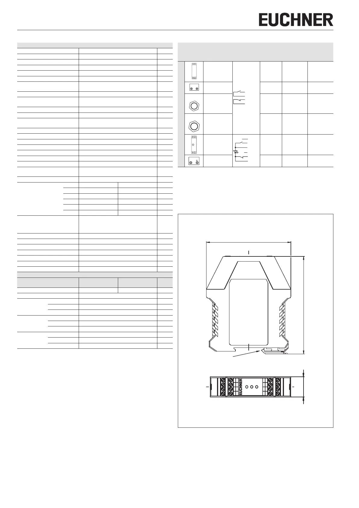
Combination options for evaluation unit CMS-E-ER
Design Read head
Circuit dia-
gram, not
actuated
3)
Actuator
Assured oper-
ating distance
s
ao
[mm]
4)
Assured
release
distance s
ar
[mm]
Evaluation unit CMS-E-ER
CMS-R-AXH/-SC
5)
WH
BU (GN)
CMS-M-AC 6 31
CMS-R-BXI/-SC CMS-M-BD 3 12
M25
CMS-R-CXC/-SC CMS-M-CA 6 14
M30
CMS-R-EXM/-SC CMS-M-EF 6 17
CMS-RH-AYA-…L
PK
WH
BK
GY NC
CMS-MH-AA 10 20
CMS-RH-BYB-…L CMS-MH-BB 6 13
3) Old conductor coloring in brackets.
4) There must be no ferromagnetic material in the vicinity of the read head or the actuator.
All data refer to the frontal approach direction and a center offset of m = 0.
5) The minimum operating distances S
omin
between read head and actuator are 1mm. If the distances
are less than this, the evaluation unit changes to the fault state.
Figure 1: Dimension drawing for evaluation unit CMS-E-ER
114
22,5
K2
K1
Power
Safety Switch CMS
14
32
Y1
Y2
Y3
23
13
31
A2
24
H12
H74
H73
H22
H11
A1
Suitable for 35mm mounting rail acc. to DINEN60715 TH35