9
Operating Instructions
Evaluation Unit CMS-E-ER
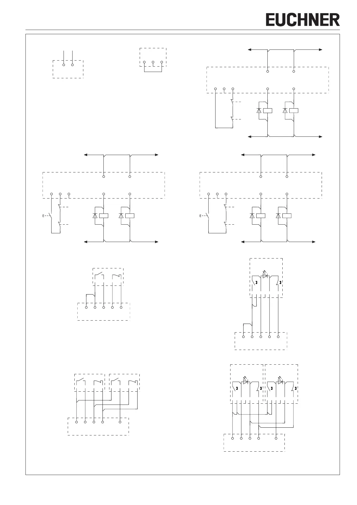
Operating voltage connection Connection for automatic start
without feedback loop
Connection for automatic start
with feedback loop
Betriebsspannung/
operating voltage
A2A1
feedback loop
Y1 Y2 Y3
Rückführkreis /
Feedback loop
Y1 Y2 Y3
K5
K6
14 24
13 23
K5 K6
Manual start using start button with falling edge and connected feedback loop Manual start using start button with rising edge and connected feedback loop
Rückführkreis /
Feedback loop
Y1 Y2 Y3 14 24
13 23
K5 K6
K5
K6
Rückführkreis /
Feedback loop
Y1 Y2 Y3
K5
K6
14 24
13 23
K5 K6
Wiring diagram for one read head CMS-R-… Wiring diagram for one read head CMS-RH-…
BN WH BU BK
Read Head 1
H12 H73H11 H74H22
1 Lesekopf / 1 Read Head
gn
BKBU
-
PK WHBN
+
GY
NC
Read Head 1
H12 H73H11 H74H22
1 Lesekopf / 1 Read Head
Wiring diagram for 2 read heads CMS-R-… Wiring diagram for 2 read heads CMS-RH-…
BN WH BU BK
Read Head 1
BN WH BU BK
Read Head 2
H12 H73H11 H74 H22
max. 2 Leseköpfe / max. 2 Read Heads
gn
BKBU
-
PK WHBN
+
GY
NC
Read Head 1
gn
BKBU
-
PK WHBN
+
GY
NC
Read Head 2
H12 H73H11 H74 H22
max. 2 Leseköpfe / max. 2 Read Heads
The following applies to all the illustrations:
f Evaluation unit electrically isolated
f Actuator not in the actuating range
Figure 2: Wiring diagram for CMS-E-ER, part 1 (continued on next page)