Euphonix ML530 Mic-Line Interface Operation Manual
10
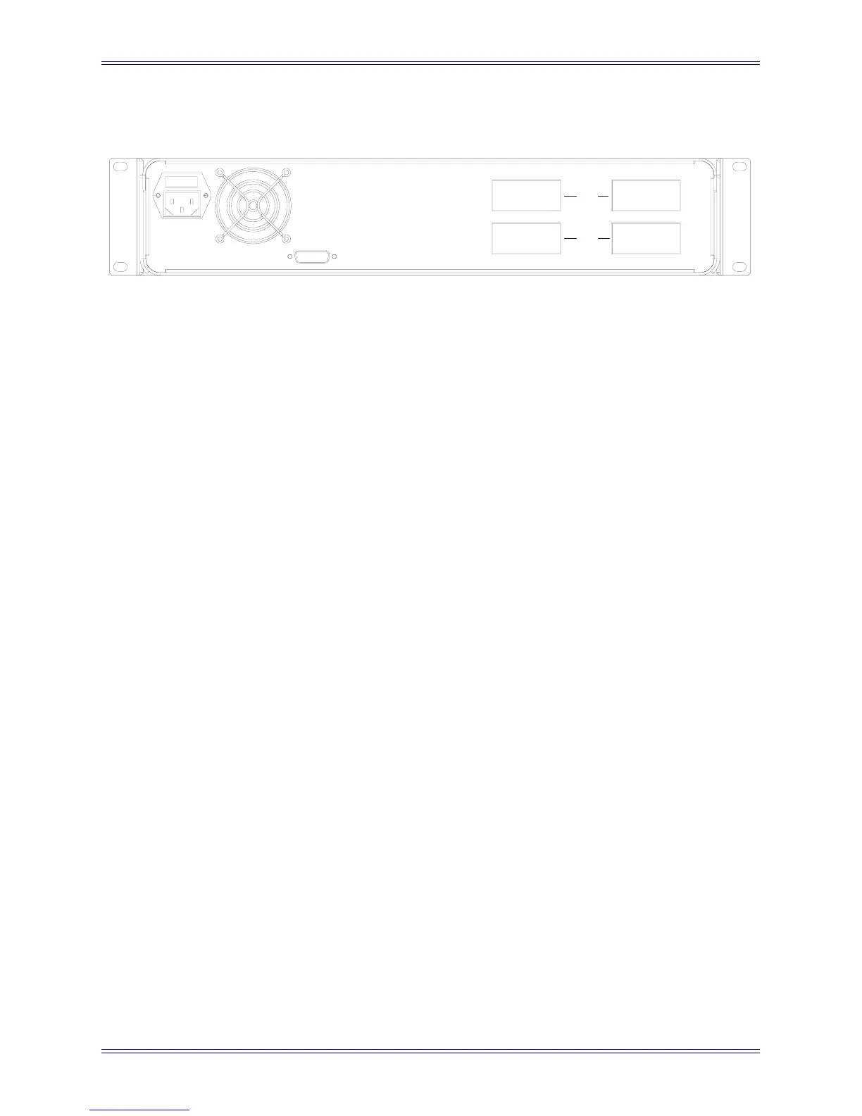
Rear Panel
Figure 3 ML530 Rear Panel
Inputs (38-pin Elco): 24 inputs are provided on two 38-pin ELCO connectors. The lev-
el of all signals input at these ports can be boosted or attenuated. In standard configu-
ration, the input cable is configured by customer. Elco connectors and pins are
provided. See Elco 38 Input/Output Pinout on page 17.
Outputs (38-pin Elco): 24 outputs are provided on two 38-pin Elco connectors. The
supplied output cables fan out to two sets of 12 male XLRs for connection to the
AM713 Analog to MADI converter. See Elco 38 Input/Output Pinout on page 17.
Control (DB-15): Input for digital control signal from PC253i Digital Pilot. Signal for-
mat is Euphonix TCC bi-directional serial protocol. All switching and gain controls are
communicated via this connector.
AC Line In (IEC) and Fuse Tray: The power connector accepts standard IEC power
cords. 90–250 VAC 110, 220, or 240 VAC, 50/60 Hz can be applied at this connector.
CONTROL
OUTPUTS INPUTS
1-12
13-24
ML530
 Loading...
