Euphonix ML530 Mic-Line Interface Operation Manual
9
Front Panel
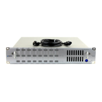
Figure 1 ML530 Front Panel
Power Switch: The power switch, on the lower right, turns the unit on/off.
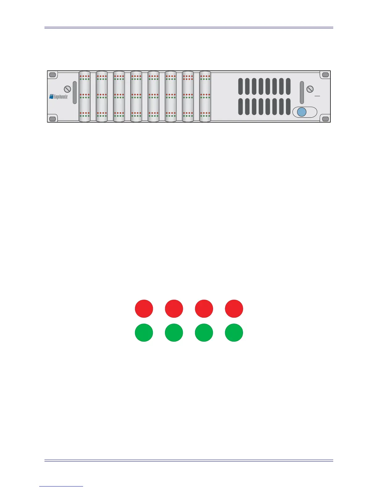
Status LEDs: Eight LEDs provide status information for each of the 24 channels:
• Clip: Signal clipping (red)
• Mute: Channel muted (red)
• HiZ: High impedance (red)
• 48V: Phantom power (red)
• Sig: signal present (green)
• HPF: High-pass filter (green)
• Phase: Phase invert (green)
• Pad: 12 dB attenuation (green)
Figure 2 Front Panel Channel Status LEDs
Since the ML530 is digitally controlled via software, the power switch is the only front
panel control.
MIC LINE INTERFACE
ML
530
12345678
910111213141516
17 18 19 20 21 22 23 24
Clip Mute LowZ 48V
Sig HPF Phase Pad
 Loading...
