Euphonix ML530 Mic-Line Interface Operation Manual
15
Optional Input Patch
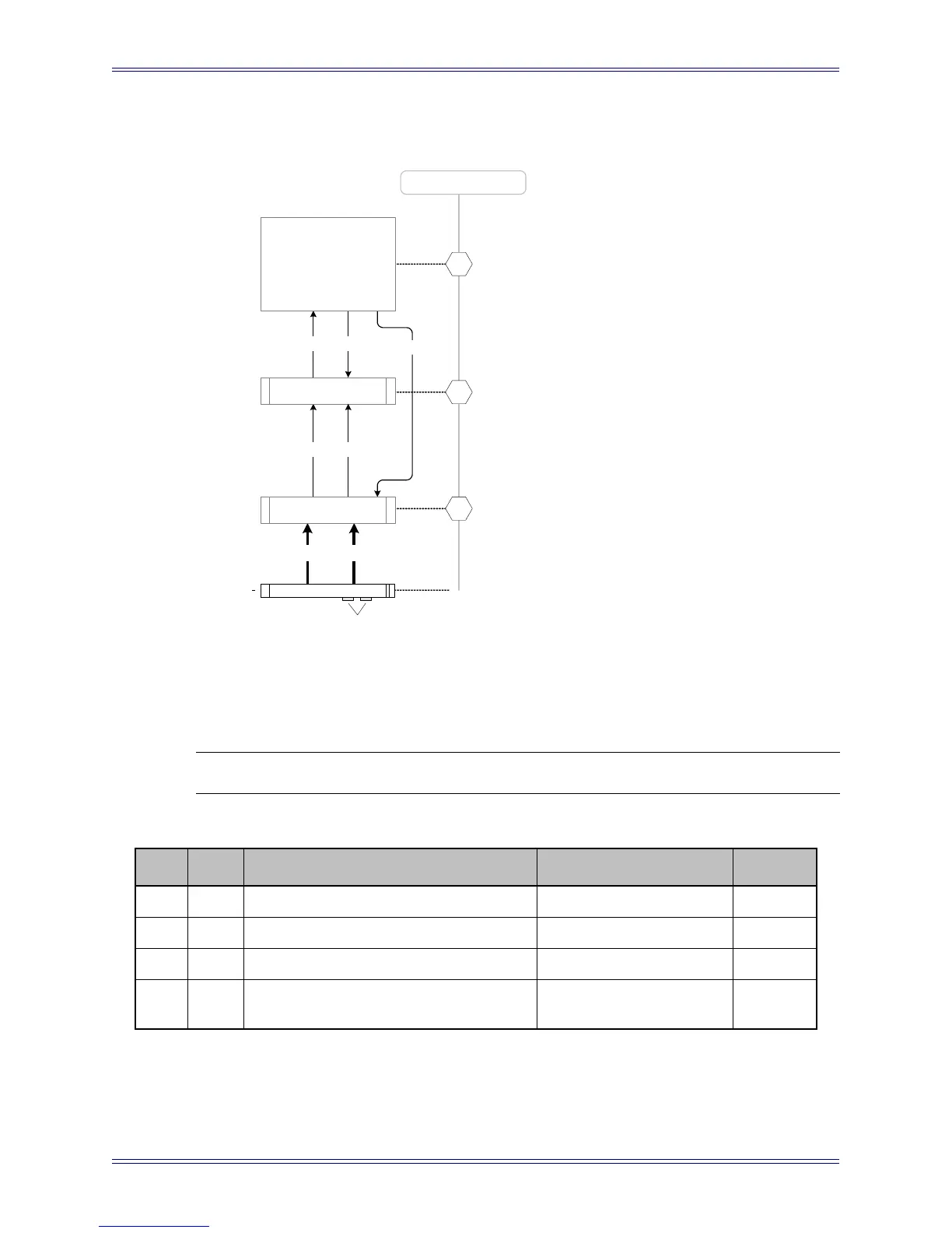
Figure 6 Input Patch Cable Diagram
NOTE: Patchbay, cables, pins and connectors are ordered separately as required.
Table 5 Input Patch Cable Specifications
*Elco hoods and crimp pins are included in standard 10M and 20M accessory cable kits.
**10M cable available, one male Elco 38 <> one male Elco 38, part# 030-06913-01
Part Qty Description Part # Length
A 1 Tie Line Patch 950-03770-01 NA
B* 2 Elco 38-Pin Connector w/hood 100-02099-00 NA
C* 80 Elco Crimp Pins 100-02100-00 NA
D** 2
ML530 Analog Out
one male Elco 38 <> one male Elco 38
030-07158-01 2 m
5 5
4
21
B
recommended locations
3
AM713
ADigital Core
B
Mic-Line Input Patch
4
ML530
Note: The optional input patchbay has the
capacity to provide input patching to 48
channels or two ML530 Interfaces. An
additional set of cable D is required for the
second ML530 interface.
Input cabling supplied
by customer
DD
A
B, C
 Loading...
