•
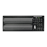
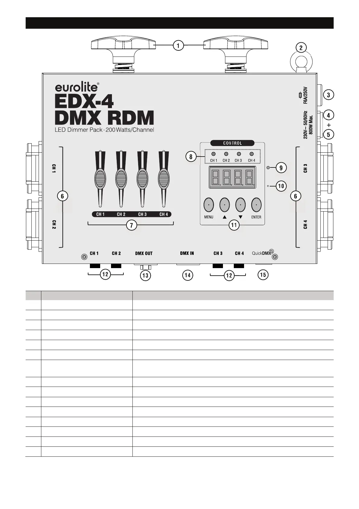
OPERATING ELEMENTS AND CONNECTIONS
No.
Element Function
1 Fixation screws For mounting on a truss.
2 Safety eyelet For fastening a safety rope.
3 Fuse holder To protect the mains input.
4 P-Con power input For connection to the 230 V mains via the mains cable provided.
5 P-Con power output For power supply of further devices.
6 Earthed sockets CH 1-4 For connection to the LED lamps to be controlled.
7 Sliding controls CH 1-4 For adjusting the brightness of the individual dimmer channels in
"Manual" mode and for switching on/off in switch mode.
8
Channel indicators CH 1-4 Light blue when the respective channel receives a control signal.
9
DMX indicator Lights continuously when a DMX signal is received.
10
Microphone For sound control in “Music“ mode.
11
Control unit The device offers 4 control buttons and an LED display for configuration.
12
Fuse holders CH 1-4 To protect the outputs CH 1 to CH 4.
13
DMX output 3-pin XLR female socket, used to send DMX data
14
DMX input 3-pin XLR male socket, used to receive DMX data.
15
USB port For connecting a QuickDMX wireless receiver.
 Loading...