C a s t l e C a r e -Te c h Pa g e : 1 3
C
onnections
Resistor
Input Wiring
ALARM TAMPER
+AUX-
Input 2
Detector
BELL
BUS
BATTERY
AUX
+12V GND
PGM AUX+ SPK STB BELL TR B- B+
4
K
7
4
K
7
Spare N/C Contact
Input 1
Door Contact
4
K
7
4
K
7
Remove for DP
ALARM TAMPER
+AUX-
Input 2
Detector
BELL
BUS
BATTERY
+12V GND
AUX
PGM AUX+ SPK STB BELL TR B- B+
4
K
7
2
K
2
Spare N/C Contact
Input 1
Door Contact
2
K
2
4
K
7
Remove for DP
This link
should be ON
This link
should be ON
Z1 COM Z2 COM +12V Z3 COM Z4 Z5 COM Z6 COM +12V Z7 COM Z8 Z9 COM Z10 D1- D2+ D3 D4 - BAT + GND
Z1 COM Z2 COM +12V Z3 COM Z4 Z5 COM Z6 COM +12V Z7 COM Z8 Z9 COM Z10 D1- D2+ D3 D4 - BAT + GND
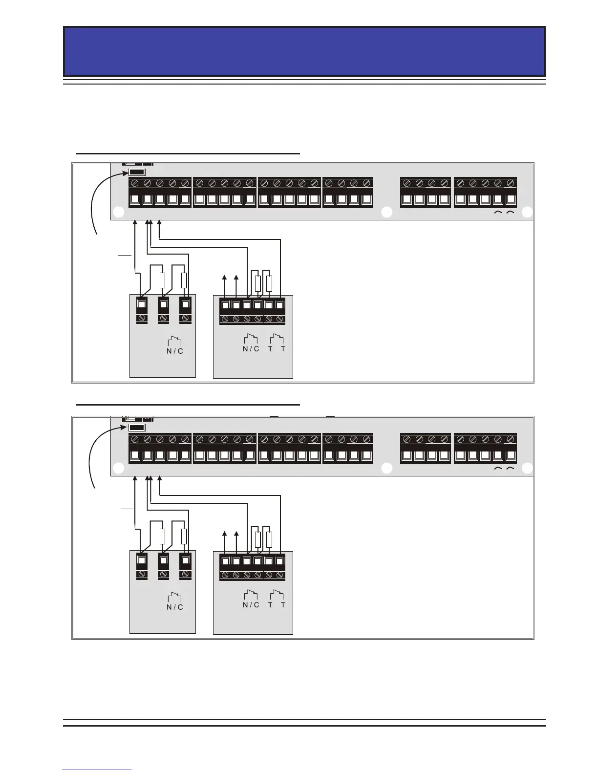
If double end of line is used, the link above input 1 (shown below) needs to
be closed, and specic resistors need to be used depending on which mode is
selected (see Choose Mode in the programming manual). There are 2 choices:
ALARM TAMPER
+AUX-
Input 2
Detector
BELL
BUS
BATTERY
AUX
+12V GND
PGM AUX+ SPK STB BELL TR B- B+
4
K
7
4
K
7
Spare N/C Contact
Input 1
Door Contact
4
K
7
4
K
7
Remove for DP
ALARM TAMPER
+AUX-
Input 2
Detector
BELL
BUS
BATTERY
+12V GND
AUX
PGM AUX+ SPK STB BELL TR B- B+
4
K
7
2
K
2
Spare N/C Contact
Input 1
Door Contact
2
K
2
4
K
7
Remove for DP
This link
should be ON
This link
should be ON
Z1 COM Z2 COM +12V Z3 COM Z4 Z5 COM Z6 COM +12V Z7 COM Z8 Z9 COM Z10 D1- D2+ D3 D4 - BAT + GND
Z1 COM Z2 COM +12V Z3 COM Z4 Z5 COM Z6 COM +12V Z7 COM Z8 Z9 COM Z10 D1- D2+ D3 D4 - BAT + GND
DEOL: 4K7 Alarm, 2K2 Tamper
DEOL: 4K7 Alarm, 4K7 Tamper