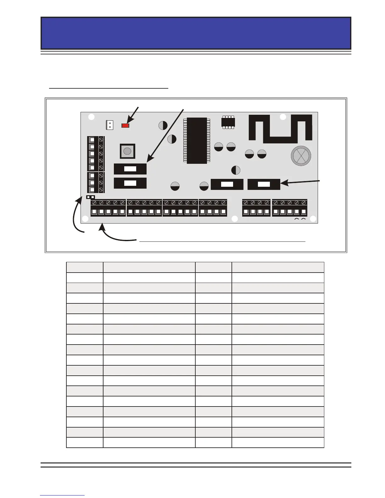
Z1 COM Z2 COM +12V Z3 COM Z4 Z5 COM Z6 COM +12V Z7 COM Z8 Z9 COM Z10 D1- D2+ D3 D4 - BAT + GND
BELL
BUS
BATTERY
AUX
Remove for DP
PGM AUX+ SPK STB BELL TR B- B+
Fuses
Fuses
Power LED
(flashes)
Double Pole
Link
The Z1 and Z2 GND terminal cannot be used as 0V
PGM Output 1 Z6 Input 6
AUX+ +12V Supply COM 0V/Common
SPK Speaker Output +12V +12V Supply
STB Output 2 Z7 Input 7 / Output 4
BELL Output 3 COM 0V/Common
TR Siren Tamper Return Z8 Input 8 / Output 5
B- 0V Z9 Input 9 / Output 6
B+ +12V Supply COM 0V/Common
Z1 Input 1 Z10 Input 10 / Output 7
COM Common Only D1- RS485 Bus: 0V
Z2 Input 2 D2+ RS485 Bus: +12V
COM 0V/Common D3 RS485 Bus: Data A
+12V +12V Supply D4 RS485 Bus: Data B
Z3 Input 3 -BAT Battery Negative
COM 0V/Common BAT+ Battery Positive
Z4 Input 4 GND Earth
Z5 Input 5 ~ 17V Input
COM 0V/Common ~ 17V Input
The EURO mini printed circuit board is as follows: