L30C-30A-UK-02-01 2 May 2009
3. CONNECTION OF TANKS
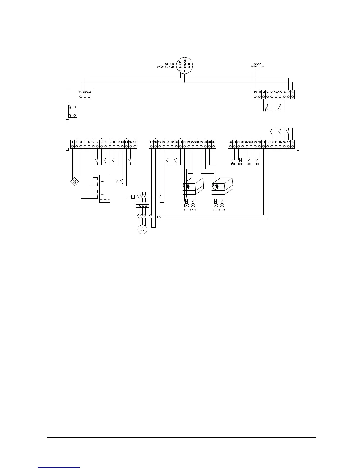
0V+AN0: Conductivity input, analog A0+0V: Conductivity output, analog
0V+AN1: Available input, analog
1+2: I0 Water meter 25+26: O0 Sol 1 T1
3+4: I1 LS min. 27+28: O1 Sol 2 T1
5+6: I2 LS max. 29+30: O2 Sol 1 T2
7+8: I3 External operation request 31+32: O3 Sol 2 T2
9+10: I4 External regeneration start 33+34: O4 Outlet valve T1
11+12: I5 Block automatic regeneration 35+36: O5 Outlet valve T2
13+14: I6 Pressure switch 37+38: O6 RO inlet valve
15+16: I7 Block operation 39+40: O7 RO quality rinse valve
17+18: I8 RO pump in operation 41+42: O8 RO pump
19+20: I9
RO protective motor switch, disconnected
43+44: O9 Alarm (potential-free)
21+22: I10 Conductivity = OK 45+46: O10 Dosing (potential-free)
23+24: I11 Alarm reset 47+48: O11
Output configuration (potential-free)
49+50 Supply 24 VDC
51+52+53
Regeneration, softening (potential-free)
54+55+56 Alarm (potential-free)
57+58 24 VDC miscellaneous