10
ATC-E, ATC-ES, ATWB, eco-ATWB and eco-ATWB-E Evaporative Condensers and Closed Circuit Coolers
Assembly of the Coil/Fan Section to the Basin (Cont.)
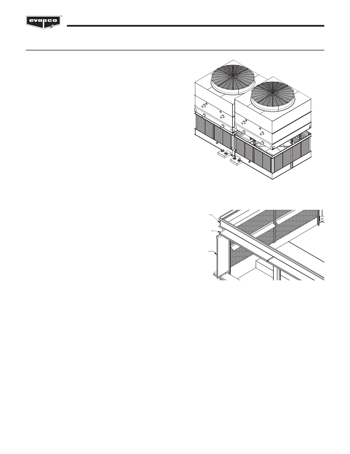
Use of Drift Pins for Final Positioning
Drift pins are tools used to align holes in the flanges of the
u
pper and lower sections of the unit prior to final fastening. By
the time drift pins are needed, the lower section of the unit has
already been anchored to its support structure. The sealer tape
has been laid down on the lower section’s flanges, and the
upper section is now hovering over the lower section.
A drift pin should be driven in to each of the corner bolt holes
such that the upper and lower flanges are aligned as best as
possible with sideways motion restricted.
On units which are longer than 12’ (“L” > 12' [3.7m]), a drift pin
should be used at an intermediate pair of bolt holes in the
rigging seam to allow for proper alignment.
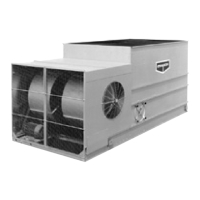
VERTICAL
SPLASH
GUARD
PAN SECTION
SIDE PANEL
FILLER CAP
CHANNEL
Figure 9 - Mating Upper Section to Basin Section
Figure 10 - Filler Cap Channel Assembly
Notes:
For multi-cell units, the side flanges located in between cells
can be accessed from inside the unit.
Bolts can be driven upward through the mating flanges if
access is restricted.
All rigging hardware is provided by EVAPCO. Drift pins are
by others.