4
Low Profile Forced Draft Towers, Coolers and Condensers
Table 2 shows minimum “H” dimensions and gives “A” dimensions for the different unit sizes.
Extended Lifts
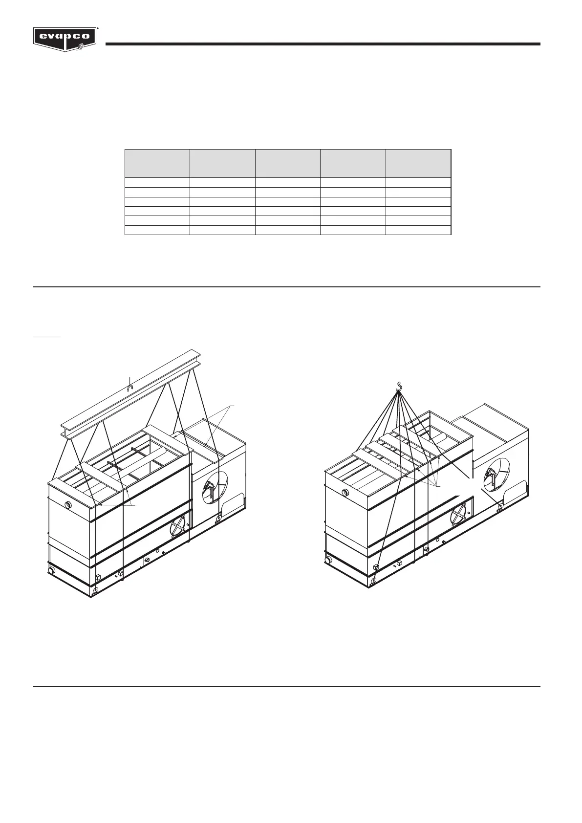
The recommended method for extended lifts is to use slings under the unit (Figures 3a and 3b). Safety slings, spreaders and skids
should be removed before nal positioning of the unit.
NOTE: Always use safety slings for extended lifts or where any safety hazard exists.
Applying Sealer Tape
If the unit was shipped with optional discharge attenuation or discharge hoods sealer tape must be applied prior installation of
the section. Once the unit has been set on the supporting steel and bolted in place, wipe the top anges to remove any dirt or
moisture. Place sealer tape over the mounting hole centerline on the side anges. Apply two strips of sealer tape, one partially
overlapping the other, on the end anges.
Coil/Casing
Footprint
A
Towers
A
Coolers
Condensers
H1 H2
3’ x 6’ (0.9 x 1.8 m) 86” (2,185 mm) 86” (2,185 mm) 3’ (915 mm) 10’ (3,050 mm)
5’ x 6’ (1.5 x 1.8 m) 102” (2,590 mm) 102” (2,590 mm) 5’ (1,525 mm) 12’ (3,660 mm)
5’ x 9’ (1.5 x 2.7 m) 137” (3,480 mm) 137” (3,480 mm) 5’ (1,525 mm) 13’ (3,960 mm)
5’ x 12’ (1.5 x 3.6 m) 174” (4,420 mm) 174” (4,420 mm) 5’ (1,525 mm) 14’ (4,270 mm)
8’ x 9’ (2.4 x 2.7 m) 138” (3,505 mm) 133” (3,380 mm) 7’ (2,135 mm) 17’ (5,180 mm)
8’ x 12’ (2.4 x 3.6 m) 174” (4,420 mm) 169” (4,290 mm) 7’ (2,135 mm) 20’ (6,100 mm)
Table 2 – Dimensional Guidelines for Lift Cables.
Dimensions Refer to Drawings in Figure 2a and 2b.
SPREADER
BAR
SPREADER
BARS
SPREADER
BAR
Figure 3a – Recommended Safety Sling Rigging Figure 3b – Alternative Safety Sling Rigging


 To Next Page