5
Low Profile Forced Draft Towers, Coolers and Condensers
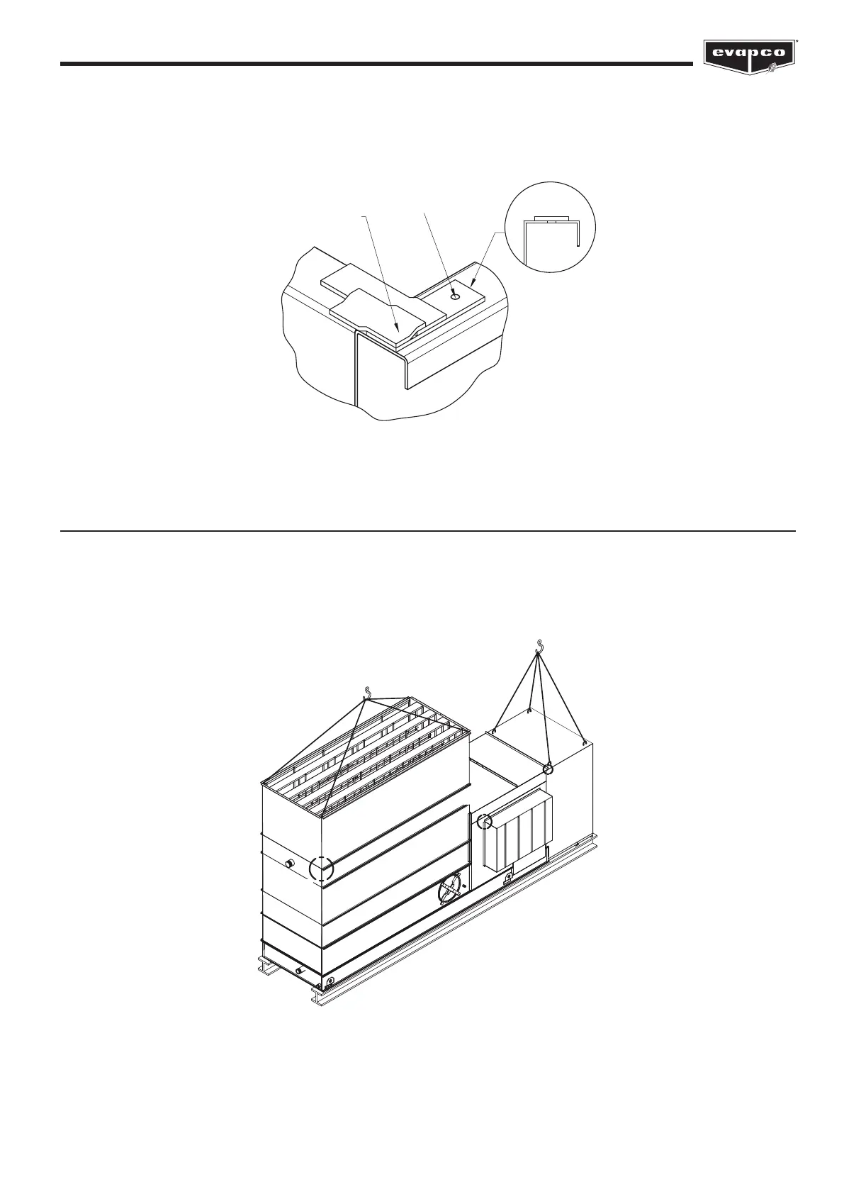
The sealer tape should overlap on the corners as shown in Figure 4. Do not splice the sealer tape along the end anges and
preferably not on the side anges if it can be avoided. Always remove the paper backing from the sealer tape.
Rigging and Assembling Discharge and Intake Accessories
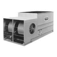
Intake sound attenuators and discharge hoods/discharge attenuators are not assembled to the main unit when shipped and must
be separately rigged and assembled in the eld. Four accessories fall into this group - discharge hood (may be straight or tapered),
discharge attenuation, fan-end sound attenuator and fan side attenuators. These are shown mounted in Figure 5 and construction
details are referenced to Figures 7, 9 and 11 respectively.
2 OVERLAPPING
LAYERS OF SEALER
ON THE ENDS
END
1 LAYER OF SEALER
CENTERED OVER THE
MOUNTING HOLES
SIDE
Figure 4 – Proper Sealer Tape Application
Hood or attenuation only
Figure 5 – Discharge and Intake Accessory Rigging
FIG. 7
FIG. 11
FIG. 9


 To Next Page