6
Low Profile Forced Draft Towers, Coolers and Condensers
Rigging Discharge Hoods and Discharge Attenuators
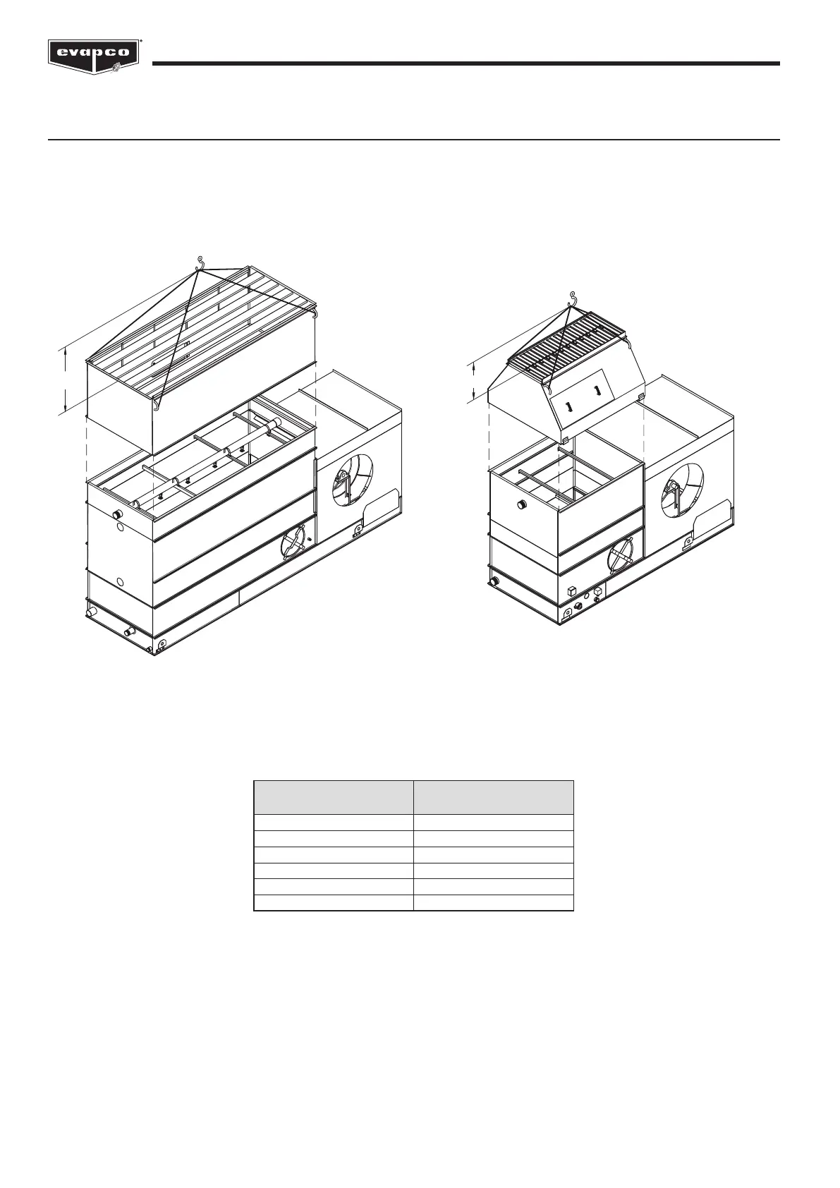
Discharge Hoods may be either straight or tapered. Discharge Attenuators will be straight-sided. Both must be rigged with a
separate lift after the main unit has been secured to the structural supports. The rigging for both types of accessories is shown in
Figures 6a and 6b. The lifting cables must be long enough to allow the crane hook to be a minimum dimension “H” above the top
of the assembly. These “H” values are given in Table 3.
H
H
Figure 6a – Rigging Straight Discharge Hood or
Discharge Attenuation
Figure 6b – Rigging Tapered Discharge Hood
Coil/Casing
Footprint
H
3’ x 6’ (0.9 x 1.8 m) 8’ (2,440 mm)
5’ x 6’ (1.5 x 1.8 m) 8’ (2,440 mm)
5’ x 9’ (1.5 x 2.7 m) 10’ (3,050 mm)
5’ x 12’ (1.5 x 3.6 m) 15’ (4,570 mm)
8’ x 9’ (2.4 x 2.7 m) 10’ (3,050 mm)
8’ x 12’ (2.4 x 3.6 m) 15’ (4,570 mm)
Table 3 – “H” Dimensions for Discharge Hoods


 To Next Page