7
Low Profile Forced Draft Towers, Coolers and Condensers
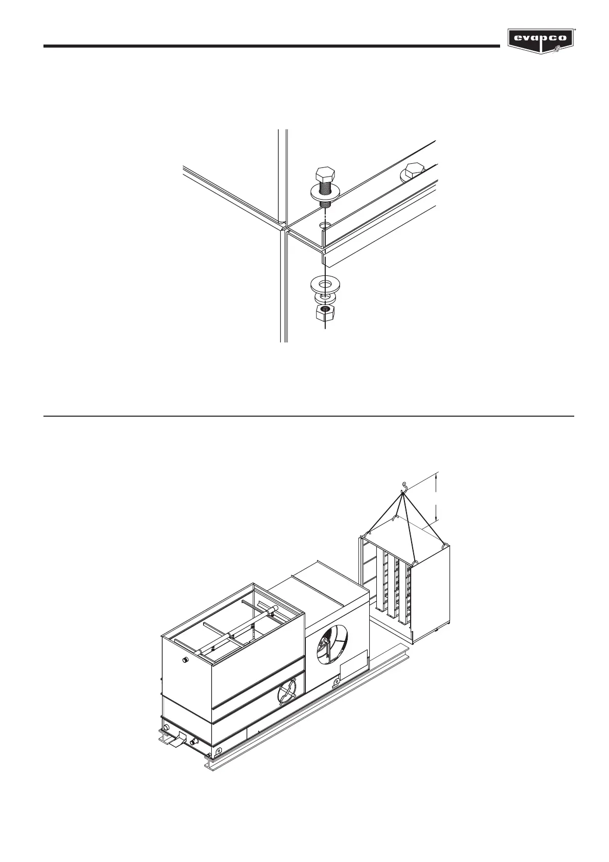
On galvanized and stainless steel units use 5/16” (M8) nuts and bolts to secure the hood or attenuation to the casing. Con-
struction details referenced in Figure 5 are shown in Figure 7 below.
Rigging Fan End Sound Attenuation
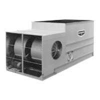
Fan end sound attenuators must be rigged with a separate lift after the main unit has been secured to the structural supports. The
rigging for the fan-end sound attenuator assembly is shown in Figure 8. The lifting cables must be long enough to allow the crane
hook to be a minimum dimension “H” above the top of the assembly. These “H” values are given in Table 4.
Figure 7 – Discharge Hood or Attenuation Assembly Details
Figure 8 – Rigging Fan-End Sound Attenuator Assembly
H


 To Next Page