8
Low Profile Forced Draft Towers, Coolers and Condensers
Coil/Casing
Footprint
H
3’ x 6’ (0.9 x 1.8 m) 4’ (1,220 mm)
5’ x 6’ (1.5 x 1.8 m) 5’ (1,525 mm)
5’ x 9’ (1.5 x 2.7 m) 5’ (1,525 mm)
5’ x 12’ (1.5 x 3.6 m) 5’ (1,525 mm)
8’ x 9’ (2.4 x 2.7 m) 8’ (2,440 mm)
8’ x 12’ (2.4 x 3.6 m) 8’ (2,440 mm)
Table 4 – “H” Dimensions for Fan-End Sound Attenuator Assembly
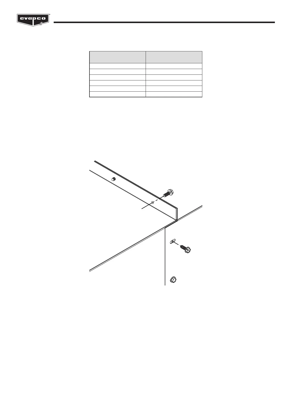
On galvanized units, the fan-end sound attenuator housing is secured on the sides and top with 5/16” (M8) self-tapping bolts. On
stainless steel units, the fan-end sound attenuator housing is secured on the sides using 1/4” (M6) threaded machine bolts that are
set into rivnuts located in the side panel of the main unit and on the top using 5/16” (M8) stainless steel nuts and bolts. Construction
details referenced in Figure 5 are shown in Figure 9. At the time the fan-side attenuator is tted to the main unit, be sure that the fan
belt adjustment extension tube at the base of the fan-end sound attenuator assembly is properly mated with the hex head tting at
the main unit.
Figure 9 – Fan-End Sound Attenuator Assembly Details


 To Next Page