2
PMC & eco-PMC SERIES FORCED DRAFT EVAPORATIVE CONDENSERS
flange and the beams as this will not provide proper longitudinal support.
NOTE: Consult the latest IBC code for required steel support layout and structural design.
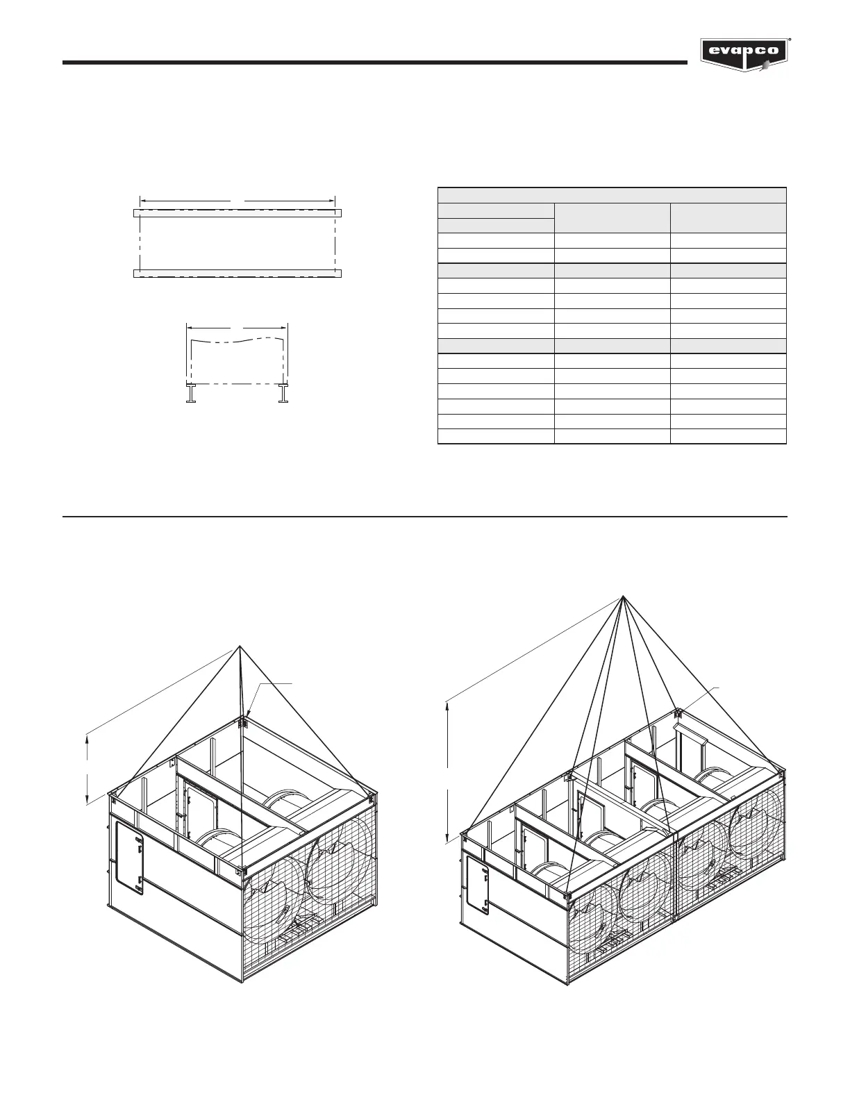
Figure 1 – Structural Steel Support
A
B
Plan View
End Elevation
H
LIFTING
U-BOLTS
H
LIFTING
U-BOLTS
Figure 2 – Basin & Fan Section
(up to 20’ Long)
Figure 3 – Basin & Fan Section
(over 20’ Long)
Rigging the Basin & Fan (Bottom) Section — Standard Li
U-bolts or similar liing points are located in the basin and fan section for liing and final positioning purposes as shown below in Figures
2 and 3. Units with lengths up to 20’ have 4 total li points. Units with lengths over 20’ long units have either 6 or 8 li points. See Table
2 for the minimum “H” dimensions for rigging the basin and fan assembly. Always use safety slings for extended lis or where any hazard
exits. See the “Extended Lis” section in this bulletin.
NOTE: Use all of the U-bolts or li points provided for liing.
Table 1 – Steel Support Dimensions
(See Table 2 for model numbers corresponding to box size)
PMC-E, eco-PMC
Box Size
A B
5’ Wide Models
5’ x 12’ 11’ 11-5/8” 6’ 4”
5’ x 18’ 18’ 1/8” 6’ 4”
10’ Wide Models A B
10’ x 12’ 11’ 11-3/4” 9’ 9-3/4”
10’ x 18’ 18’ 1/8” 9’ 9-3/4”
10’ x 24’ 24’ 7/8” 9’ 9-3/4”
10’ x 36’ 36’ 2” 9’ 9-3/4”
12’ Wide Models A B
12’ x 12’ 11’ 11-3/4” 11’ 10-3/8”
12’ x 18’ 18’ 1/8” 11’10-3/8”
12’ x 20’ 20’ 1/4” 11’ 10-3/8”
12’ x 24’ 24’ 7/8” 11’ 10-3/8”
12’ x 36’ 36’ 2” 11’ 10-3/8”
12’ x 40’ 40’ 2” 11’ 10-3-8”